Miscellaneous Notes
Miscellaneous notes from front of car towards the back - taken mostly from The Jag-lovers Forum with my own additions
Stuck Bonnet Release:
The bonnet is released by two standard releases - one on each side near the bulkhead. If the cable breaks there is no obvious way of releasing the bonnet.
I understand the early XJ's had a large grommet under the inner wing through which it was possible to poke a screwdriver to release the locking mechanism. On later models, I believe it is necessary to remove the inner wing retaining button and drill out the hole to 25 mm (1 inch) - again releasing the locking mechanism with a screwdriver. Re-secure the plastic inner wing after making a new hole for the retaining button close to the original.
External Temperature Sensors:
These are located in the brake cooling ducts, behind the front bumper and in front of the wheel arch liner. Access can be obtained by removing the front under tray.
The left hand sensor is used as input to the climate control system. The right hand sensor is used to control the washer reservoir heater and washer jet heaters, active below 4°C, and to control the heated seats, active below 26°C.
Air Conditioning radiator:
Failure of the condenser is one of the most common reasons for loss of refrigerant, as it is quite exposed at the lower front of the car. The filter/drier is mounted above the condenser and needs the condenser to be removed for replacement.
To remove the condenser, first remove the radiator top panel which crosses the width of the car at the front of the bonnet area. It is secured by a number of large torx bolts which appear to frequently seize up. If necessary, they will need to be drilled out, or the heads ground off, but fortunately load on this panel is not high and loss of one or two bolts does not appear to be a problem.
Locate the pipes leading to the condenser as they pass to the side of the main radiator. The union for one pipe is a few inches into the main engine bay whereas the second is on the filter/drier unit, mounted on top of the condenser and therefore harder to access. Undo the unions slowly, listening for refrigerant pressure. If there is any pressure, then you don?t have a leak and the condenser doesn't need replacement.
The top of the main engine radiator can be pushed gently backwards and the condenser & filter/drier then removed by pulling them upward. On XJR models, the upper hose for the intercooler radiator, mounted in front of the condenser, makes this more difficult but it is just possible without removing the hose.
The area around the mounting lugs for the condenser is a known rust spot and so you may consider treating it with a rust-proofing agent prior to refitting.
If you have to replace the condenser, replace the filter/drier at the same time as these do become saturated and otherwise need replacement on their own.
When refitting the condenser, carefully lower it into the space and from underneath ensure it is settled correctly onto the locating rubber grommets. Reattach the pipe work and refit the top panel. The system works at high pressure so ensure O-rings are in good condition and ensure unions are tight during refitting. Always use two spanners on the union to avoid stresses other parts of the pipe work when loosening or tightening the unions.
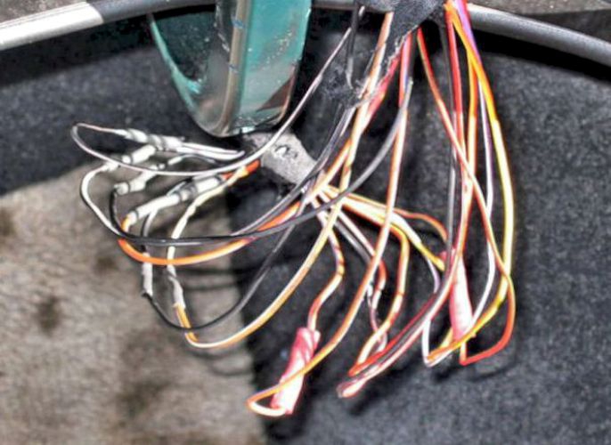
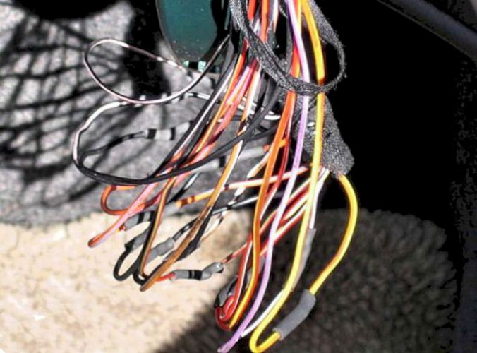
Fans should be running all the time:
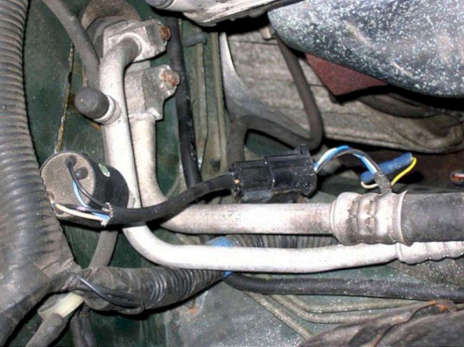
For slow speed running, the relay connects the two fans in series so that each fan runs on 6 volts and therefore runs more slowly. If one fan is open-circuit or has a broken connection, then neither fan will run when connected in series for slow-speed running. So if fans are not running at low speed when they should be, check that BOTH fans run at high speed.
Fuses are in the left-hand engine bay fuse box #11 and #17 and are both have a 30 amp rating.
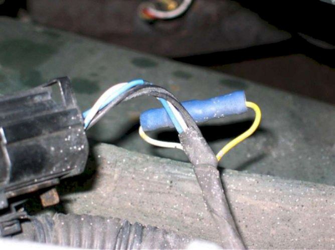
An official modification was to permanently connect together the wires that originally went to the single-pressure switch (which was mounted on the a/c pipes next to the offside bulkhead). This is the bullet connector in the second photo and means that the radiator fans should run at low speed all the time the ignition is on in order to keep the air conditioning radiator (in front of the car radiator) cool. If the radiator temperature exceeds 100°C then both fans should run at full speed.
Testing front sub-frame V mounts:
The easiest way is with a pry bar. Simply place it near the V- Mount, in the gap between the front cross member and the body, and see if you can separate the two. V-Mounts fail when the rubber between the two metal brackets fail, so if they are bad, you will see movement.
Front Shock Absorber Replacement Bushings:
The upper bushings are a known weak point, particularly on the left side of the car where heat from the coolant header tank is thought to affect them. Feel above shock at top of body. If the bushing is deformed, or there is space then you probably have a half or three quarter inch of travel before the shock absorber begins to work. There will probably also be a bump as it hits the body work.
It is vital to be really careful when replacing the bushes or shock absorbers as the shock absorber is only thing which holds the spring in place. The risk is that if the lower suspension drops too far, then the spring can come out sideways with a lot of energy and cause serious injury.
To perform the task, first slightly loosen, but do not remove, the top locknut, using a vice grip or similar if necessary in the top of the wheel arch to stop the shock absorber rod turning. Put the car up on a stand and then raise the lower suspension arm using a jack near the balljoint and then use a second stand or similar to raise up the suspension a little and so prevent the spring escaping.
If replacing the shock absorber itself, undo the nut and bolt attaching the lower end of the unit to the lower control arm. This is not necessary if just the bushings are being replaced.
Now undo the top shock absorber mount and depress the shock absorber rod itself. The existing bushing can now be removed and replaced as, where appropriate, can the shock absorber itself.
Refit the new components and tighten the top mount and, if necessary, lower mounting bolt, before releasing the suspension.
If you are not changing the shocks, and have had to use a vice to hold the rod, ensure the rod does not have any damage or burrs on it, as these will damage the seals of the shock itself when in use.
Replacing front balljoints:from a thread on Jaglovers X300 Forum
Just replaced the front balljoints on my 1995 XJ6, and wanted to pass on what I have found to be a good procedure:
- Chock rear wheels, jack up front end, place jack stand under rubber jack pad of car.
- Remove tyre, turn the wheel left/right as needed to give yourself better access to each balljoint.
- Take off just a little pressure from the lower control arm by jacking up the control arm slightly
- Start with upper balljoint. Loosen balljoint retaining nut (I used 22 mm box wrench, wished I had the socket though) until you are 2-3 full turns from taking it off.
- Insert fork balljoint separator and give it 20 whacks until the balljoint is free. At this point the wheel will lurch out towards you, so watch the fingers.
- Fully remove the main retaining nut; you may need handheld vice grips to keep the ball joint from spinning at this point.
- Remove the two balljoint mounting bolts (15 mm for my car), and swap in the new balljoint.
- Do not attach upper balljoint to hub just yet, or else you will be sorry for lower balljoint access later on.
- At this point, you should back off the main retaining nut of the LOWER balljoint until you are 2-3 full turns from taking it off (21mm for my car). This is your best shot at getting to this damned nut.
- Return to the upper balljoint installation. Screw on main retaining nut only 2-3 full turns (replacement nut was 19mm for me). This nut may need to be temporarily removed later on in the procedure if you encounter access issues with lower balljoint nut.
- Return to the lower balljoint. Ensure you have jacked up the lower balljoint just enough to slightly reduce the pressure.
- Insert fork again, and then 20 more whacks until the lower balljoint is free.
- Remove the main retaining nut of lower balljoint, should only be 2 or 3 full turns if you followed step 9. Access to the nut may be a real pain, but should be able to be completed. Try using a screw driver as a lever to wiggle the hub and control arm assembly around, until it is convenient to fit the wrench or socket in.
- Remove 4 mounting bolts (13 mm for my car), and swap in the new lower balljoint.
- Jack up the lower balljoint until the balljoint rod connects with the hub, and start the main retaining nut. Get at least 1-2 full turns on the nut. If you cannot get beyond 1-2 full turns because of access to the nut, remove the retaining nut from the UPPER balljoint assembly (should only be 2-3 turns on the nut if you followed step 10 above) and free the upper control arm from the hub. You should now be able to get a wrench in there and fully torque the lower balljoint nut.
- Fully torque the upper balljoint retaining nut. Snug up all mounting bolts (upper and lower balljoints).
- Put tyre back on, etc.
Removing the Dash (for access to the air con evaporator): from a thread on Jaglovers X300 Forum
This is one heck of a job but doable - this is a guide, not a step-by-step.
You must label all plugs and the corresponding socket - even if you think you can find them. Write every step down, it'll take three times longer but will be invaluable come rebuild.
There are a lot of cable ties so note where they go. The order may be mixed up a little but you should be able to work most of it out.
Disconnect the battery!!!!!
Remove ski slope. Remove radio/clock/climate control unit, centre console armrest etc. Unplug the Valet switch at it's plug (follow the wires) rather than prising it out of it's position in the armrest. Remove climate control dome thingy on top of dash in centre of windscreen - unplug it.
Passenger side: remove glove box, air bag cover, airbag cradle and air bag. Remove airbag module and body processor module.
Driver's side: remove lower dash and unplug aspirator.
Remove the centre air ducts along the transmission tunnel - they are gaffer taped and put up some resistance - goodness knows how they go back in. Centre vent is easily broken so make the tool and be prepared to break some vanes.
Dash side covers at doors: open doors, try to push the pegs out from the inside. Side vents: feel around for the clips (might be at the top or bottom) - depress clips and wiggle vents out.
Unclip the dash top vents and unplug tweeters. Vents can crack so be careful - might be screws here. Disconnect centre fan and heater core from all plugs to potentiometers and water in water out - catch coolant in bucket. Undo screws and disconnect black plastic air channel things to heater.
Undo four bolts/nuts under instrument binnacle and lift upwards and towards you. Unplug two plugs back of binnacle.
There are various aluminium/steel brackets/stays that need to be unbolted. The dash top is held onto the bulkhead by only a few nuts.
Take off the steering wheel after removing the air-bag. There are various black/silver modules around the drivers side of the dash that may or may not need removal to gain access to the nuts/bolts securing the evaporator. I'm not sure if the air con needs to be de-gassed to remove the two pipes in the engine bay that bolt onto the evaporator.
The lights switch/trip computer panel has have to come off to get the dash top off.
There are wiring harnesses cable tied to the dash top which need to be cut.
Lift the dash top off - maybe the A pillar trims also need to be removed? If so, unclip the chrome parts on the hand grips and
find torx screws underneath. Remove hand grips. Pull the trim off.
Reassemble in reverse order!!!
Powerfold Mirrors:
are fitted or retrofitted to some models. All the wiring is present; you also need to source the small coinholder, switch and short extension wire that fits into the drivers door. Most scrapyards will sell the mirrors but the other bits can be hard to find as they are destroyed with the rest of the car.
ALSO - be aware that the mirrors can occasionally position incorrectly, especially if they have been knocked - they will usually self-correct after a few operations so don't rush them!
Removing the Centre Console:
The dash panel that holds the radio, A/C controls etc can sometimes be found on eBay for a reasonable price. Removing the old one and replacing all the bits is not difficult.
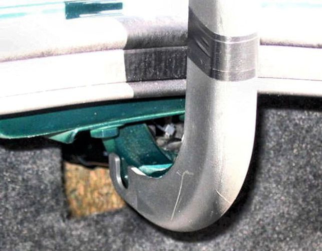
Access to Centre-Console - Ski-Slope Removal.
Put the gearlever into the neutral position.
Slide a .25mm (10thou) feeler gauge blade down on the left between the black plastic and chrome finish trim in the area slightly above the torx type plug fitting (manual override access for gearbox lock). Slip the blade in between the clip and gearshift body without straining the plastic clips as they are very brittle. Be patient, it may take a while to find the right area.
Repeat for RH side of trim then the third one in the centre at the area nearest to the ash tray, this removes the centre trim and finisher. The black trim can be gently removed upwards without squeezing.
Move the gear lever to drive position, open arm rest remove 2 screws from clip area at top of ash tray, close ash tray and lift unit up slightly then backwards to disengage ash tray assembly. Remove connection for cigar lighter (and 4.0 cars the Sport switch). There are 2 nylon wing nuts holding the ski slope in position, remove them, and save the small black plastic finisher.
Lift ski slope carefully and pull rearward and upward, carefully not to to bend it too much. It also has a tendency to stick in place. Remove completely
You can now see the linear switch that sometimes causes starting problems.
Make small adjustments of the switch and retest until you are satisfied with the operation. There is a gauge that positions this switch but it is difficult to find.
You can now access the climate control unit, clock and radio units.
Removal of this unit is simply a matter of undoing the six fixing screws and pulling the complete unit forward. Take care not to stretch or force any wiring.
Re-fitting is equally simple, but take care not to trap wires or loosen any other connectors.
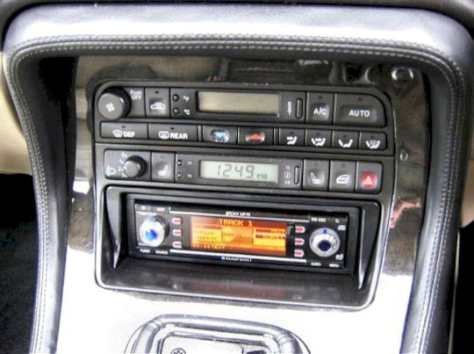
Radio/cassette - replacing with a modern CD/radio:

replacing the original radio/cassette unit (left) is fairly straightforward once the centre console is removed (above).
You will need a facia adaptor and a wiring adaptor. I got mine from eBay "JAGUAR XJ6 CD CAR STEREO FASCIA FITTING KIT 1994 - 97" which included both items for £30
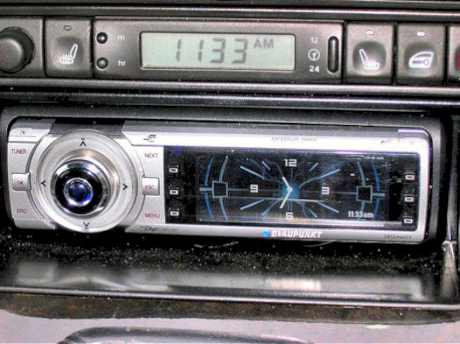
I like Blaupunkt radios and initially fitted a Memphis, but although it worked well, I thought it looked too flashy against the black Jaguar dash.
I then found a Bronx which I think matches better and looks very good in combination with the above fitting kit. Choice of display colours too.
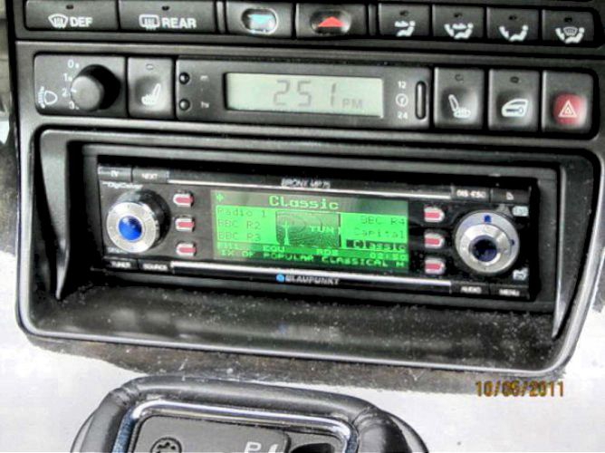
and YES, I did have a working clock at that time - but see this page :-(
X300 Key-Fob transmitter programming:
Key-ring remote Battery changing:
Caution: To avoid disrupting the coding of the key-ring transmitter, battery change must be accomplished within two minutes.
Insert a screwdriver into the slot in the rear of the key-ring transmitter near where it joins the key ring and gently push it in so as to release the clip to allow the cover to pop open
Replace the two button batteries CR2016.
Existing key-ring transmitter Re-Programming X300:
Unlock the car with the key and press ether button three times at 1 second intervals
New virgin key-ring transmitter Programming:
Open the boot/trunk lid and drivers door. Switch on the ignition to position II but do not start the engine. Wait for the dash lights to extinguish. within 5 seconds of the lights going out, Rock the valet switch, in the centre console, 5 times. The system will chirp to indicate it has entered learning mode.
On models with seat/mirror/steering wheel memory functions, the first key-ring transmitter will be linked to memory 1, second to memory 2 etc
Press and hold the larger, lock, button on the key-ring transmitter whilst watching the red LED and ether wait for it to stop flashing or for the system to chirp a confirmation it has got the signal. If the system doesn't receive any signals for 15 seconds, it will chirp twice and exit learn mode
To program further key-ring transmitters, rock the valet switch once. The system will chirp twice for remote number two, three times for number three etc, then press the lock button of the key-ring transmitter as above
When finished, wait 15 seconds for the system to time out and chirp twice, turn off the ignition, close the doors and boot lid.
Sliding Roof jammed: Jeff Watson; Sydney, Oz.
If you can tilt the sunroof open remove the inner trim piece, it just pulls out of the opening, and then you will see three Torx bolts securing the sunroof panel to the mechanism on each side. If you remove the panel will be able to examine the mechanism as it operates and you should be able to see what is jamming it up.
Sometimes the rear trim piece attachment points on the slide mechanism break and the trim piece skews and jams in the slide tracks.
The plastic attachment point parts are not available separately to the slide mechanism, the whole tilt/slide mechanism has to be obtained, though if you have a parts car you wont have this problem. The plastic piece can be removed by sliding it all the way to the rear of the slide and re-installing a new piece from the back forwards. The roof lining at the rear has to be lowered but not removed.
Have a look at these photos I took when I was working on my sunroof, it may make things a little clearer.
Drooping Roof Lining (temporary fix): Mick - Jaglovers Forum
My headliner has sagged a little more - from one side of the car to the other in the centre of the ~ 12 inch recessed area between the end of the sunroof compartment and the rear window. The rest of the headliner from this point forward is still well attached. It hung down only a few inches but it began to bother me that it was doing this and I was afraid letting it sag would simply accelerate more sagging in the future.
I purchased a piece of pre-stained wood moulding with a wood finish close to the rest of the wood on the Jag. The moulding is 1 inch wide with the finished side convex and the flat side unfinished. It is thin (⅜" thick at the highest point of the convex surface) which makes it quite flexible.
I cut it to a length of 45¾" which is slightly longer than the distance between the headliner trim on each side of the car. I cut four ½" pieces of self-adhesive velcro plastic hooks and fixed them equally spaced along the unfinished back of the wood moulding. I sprayed the finished surface of the moulding with several coats of high gloss polyurethane to improve its appearance and make it a closer match to the Jag's high gloss wood finish.
I stuck one end into the headliner trim on one side of the Jag (flat side with velcro hooks toward the headliner) and the other end in the headliner trim on the other side of the Jag. Being slightly longer than this distance, the wood moulding bowed upward taking the general shape of the roof and pressed the headliner back up against the roof. I slid the wood moulding forward just behind the beginning of the recess behind the sunroof compartment.
The moulding is not visible unless you are sitting in the back seat and, when seen, simply looks like another moulding strip across the centre of the headliner. It doesn't completely remove the sagging but it is now barely visible.
Total cost of the repair was $1.50 since I already had the velcro hooks and the polyurethane spray. You might give it a try if you have a similar problem and want a quick, inexpensive fix.
Uncle added: Congrats on this fix. I did a similar repair on my 90. To make it permanent, I drilled four holes in the wood, and used ⅝" trim screws to screw the bow in to the headliner board. This would not damage the board in the event I wanted to change the headliner in the future.
Be careful if you do this, you do not want to drill a hole through the roof, and when you turn the screws, you do not want to pull the fabric. At the time, it was a temporary fix. I sold the car.
The rest of story is about 4 years later, I saw the 90 and it was in terrible shape. Out of curiosity I did look at my headliner bow, and it was still in place. In fact, the headliner was the best part of the interior.
The Solar Sensor:
The solar sensor is on the top of the dash, just behind the windscreen - here is an explanation of how it works:
In the morning or in the shade, when it's cooler, the a/c system comes on quietly and efficiently as expected when you start your car. If, however, it's been sitting in the sun, the a/c system comes on normally when the car starts but, after a few seconds, the blower system goes into 'high gear' to cool down the cabin quickly. Then, after the temperature has been reduced, it goes back into normal mode once again. It may not be apparent with your test methods but, as another poster has said, it's not like Jag or anyone else would install a piece that didn't have some purpose.
That sensor feeds info to the ECU that controls the cabin environment along with the thermostat and other sensors in the cabin. The "bump" detects high temps due to sunlight and tells the ECU that the sun has been shining bright into the cabin and to crank up the fan speed as soon as a cool air temp is detected in the airflow of the a/c. Once a more normal temp level is detected indicating that the super heated air has been evacuated, the system goes back into normal mode.
At least that's my understanding of it. It works that way on my car, anyway. I still recall the first time it happened after we only had the car for a week or so. It sat in the parking lot and was super warm. When the fan went into hypermode, it caught me by surprise as it was the first time it had done that. I thought I'd turned something on but it was doing it all by itself.
Seat Heaters: taken from threads on Jaglovers forums
The cable coming up from the floor onto the seat is quite bulky with many cores - far more than would be needed for just an up and down motor with no memory, lumbar or backrest functions.
Jaguar always installed all the wiring, rather than having to organise different looms according to the options and the relay base is present (but with no relay). In addition, the clock module needs the extra seat heater switches and here the plot thickens as my clock module HAS the switches (though of course it could be a s/h replacement from another vehicle).
When I plugged relays into the sockets under the seats, both relays clicked and the red tell-tales in the switches illuminated, showing that everything was there except for the actual heater elements (either failed or not present).
information from "uncle" To change the heaters, you must remove the seat covers. The heater is placed between the foam cushion and the cover.
Remove the seat, controls, cut the hog rings, remove the retaining strips, and the cover and foam assembly lifts off of the seat frame. There are a number of small metal rings that attach the cover to the foam, these must be cut to remove the cover to access the heater.
Re-installation of the cover to the foam is a little pesky, but you can do it. If you cannot find the small hog rings, use nylon wire ties which work very well.
from a Centre Exhaust cats thread: information from Pete Crespin
On the British X300 3.2's there 2 cat in the down pipe a strange configuration of the 2 pipes joining together and going into a flat muffler/exhaust box, then it splits to 2 pipes and goes through 2 more boxes in front of the axle and then through 2 more tail boxes at the rear.
I had mine "Dualled" as you call it and the flat single box is now 2 round ones side by side but staggered. It sounds a lot better and I think it has a bit more oomph!
I just did the exact same thing today, removed the rear cats but kept the under rear seat resonators and rear mufflers.
I agree it sounds awesome, luxurious quiet at cruise but open it up and what an unbelievably sound. Now it sounds like a Jaguar.
Extractor exhausts require one pipe per cylinder to be properly effective- like you get on bikes. You can get mutually reinforcing pulses in a siamesed arrangement but that's not quite the same thing.
A large primary catalyst sited close to the manifold doesn't do much for extractor effect and nor does a very compact triple siamese with very tight turns out of the exhaust port, but in the real world where Jaguars need to be refined as well as swift, the standard system works fine.
There is a photo in my album of a straight-through replacement Y pipe that AJ6 Engineering fitted to my Daimler when the standard mid cat section broke. This obviously saved me buying an expensive new mid section and still left the emissions easily good enough to pass a UK test because all the front cat and O2 feedback stuff was still present, which is what controls fuelling.
Having changed to straight through to save money, it was nice to get a fraction better performance (or so it seemed) and certainly a small measured but real mpg improvement. I was in two minds about the slightly noisier sound, although on an XJR instead of a Daimler I would have welcomed it.
All other parts remained standard.
Overhauling the Handbrake assembly: from emails by Mick Gannon:
Don't waste time greasing the hand brake mechanism - remove it as it will be seized up. Best to raise the car and place axle stands on the A frame on the suspension this gives you plenty of access to do the whole job.
Total six bolts and 3 pins with spray nuts (one-way washers with teeth to you and me). Hand brake end you can get a small hammer to remove the pin as the washer collapses. All pins have a cross hole for a split pin.
Remove adjuster nut at other end, it will be rusty. Lift prop centre bearing; 2 bolts locate spacer, remove pivot bolt and nylock nut from LH side main pivot for hand brake arm, remove cable assembly, then remove bracket. Note that there should be a rubber mount for the exhaust which is often missing.
I suggest all metal parts be wire brushed, treated with rust inhibitor paint if you desire, grease everything and reassemble. Use some 8mm washers and 3 correct size split pins to replace spray nuts.
Remove wheels and discs and clean out any dust from hand brake shoes which tend to build up dust and makes then inefficient. Adjust shoes put every thing back and finally adjust hand brake to 3 notches to hold car
About 3 hours work.
On my car at the MOT station only just passed the handbrake with 16% efficiency, both handle to arm and arm cable to quadrant pivots had rusted solid hence the total strip down. If you look at the design if anything seizes up the force applied is lost in trying to rotate the pivots first before it can pull on the cable, this has the effect that you have to apply far greater pull on the lever to get any sort of movement on the cables.
Adjustment at the shoes is also very important to remove as much travel as possible, hence the strip down. It may seem an overkill but it is things like this that are often overlooked during maintenance.
You should be able to apply the hand brake and put into drive and it should hold well; then raise the rpm the car should wind it self down before the hand brake shoes start to slip and make a loud rubbing sound. Upon dropping the rev's it should hold fast. The other test is about 1 in 6 hill. If it does not hold at any amount of force applied the lever then the shoes/drum surfaces are glazed and new shoes and the drum surface needs to be cleaned and deglazed.
To remove the brake cable from the backplate
Take most of the assembly apart first, actuator plate on outside of hub, inner thin metal plate where the cable goes into the drum etc. It's this plate that the cable goes through and seizes in.
If you pull the plastic clip off using the "wing" there is a metal fitting that splits, one part sliding into the other. Soak it in release oil and then with a pair of pliers on one part and a pipe wrench on the other and twist them in opposite directions.
Then apply a little force via a screwdriver trying to get it in between the two parts. Eventually this worked. The other side was easier and after soaking and leaving for a while the screwdriver popped it apart quite easily.
This allows the cable to be withdrawn and the lug will, just, fit through the hub casting.
Repairs to the Rear Suspension: go to this page
Changing Rear Axle bearings: advice from Jag-Lovers forum
This is a DIY job - do each side one at a time, there's a spacer inside the hub that'll be different (most likely) on each side.
You will need to replace the stub axle nuts. They have an locking insert in them and usually come apart on disassembly.
Mark the pivot bolt and lower control arm so you can reassemble keeping the rear tracking from changing.
I prefer to keep the hand brake cable attached to the hub. There's a union near the 'Y' in the cable and I fed the
halves out of the lower sub-frame.
Do not let the hub flop down off the axle on it's pivot bolt, that can damage the hand brake cable.
Have someone (or something) press on the brake pedal when loosening the stub axle nuts. They are TIGHT!
Originally, it is thought that Jaguar used a thread locking compound on the splines between the hub and stub axle. Can be difficult
to separate if they've never been serviced from new.
Only special tools are a big socket and bar to loosen the axle nut, a brass drift and hammer to remove the old bearing races and install the new ones.
In-tank Fuel Pump:
The fuel pump is inside the tank and can only be accessed via the top of the tank. Normal procedure is to remove the tank, however there are some hard-to-get-at quick couplers in the fuel lines accessed from underneath. The alternative is to cut a rectangular hole (large enough to get an arm through) in the parcel shelf above the tank.
Removal of the rear seat and parcel shelf facing is the work of a few minutes.
Although the slope of the rear window limits space available, a side cutting air powered nipper would cut the hole in a few seconds.
If the hole is big enough (to get an arm in) none of the pipe or wiring connections are a problem but do be everso aware of the sharp edges produced and wear gauntlets. You will see some pressed ribs that can be used as co-ordinates for your cutting, make them suit yourself by plottimg the job in Braille from inside the boot first. Don't cut along the back edge but use that to form a fold-up flap.
Remove the large flange on top of the tank and remove the evaporative loss flange on top of the tank. The fuel pump and filter is in the tank. Pump is JLM12204 Replace it and put everything back together.
A real problem is - FUMES. Wear a mask (pref. air fed), keep all doors open and make no sparks, this is not the time to light up a Woodbine.
If, however you wish to take the tank out, or even change the filter:
The line from the tank to the fuel filter is still available new. Buy IT! Its reasonable.
Do not attempt to move the nut on the output side of the fuel filter. Spin the filter off that said nut. That line is unobtainable.
I soaked mine after the filter was off for two days and eventually freed it. Buy if you do not own a brass tooth brush, clean the threads well, use at least if not a full bottle of never sieze at least enough that your hands will not become clean for days.
That filter you will want to change every spring, no matter if 6k or 24k for no other reason because to add more never sieze!
What you are going to find once the tank is out is a cheap hose failure. Happens to all X-300's sooner or later.
Double clamp both ends of said hose. Hey may as well put the new pump in, not a job you will ever want to do again right ;-'')
Believe it or not the return line is available at a parts store.
Darrell
OR - try this
Just a note to let you know you can change the fuel pump without removing the tank by using the sender and the fuel pump holes (tank empty). It is very fiddly but can be done; took me a few hours but new pump fitted - Brian Steel
Boot lid switch:
The microswitch behind the external release button is another common failure. Switch cleaner can revive it for a while but after three or four repeat treatments it will fail completely.
Remove the boot lid lining. The switch is connected to the harness by a green plug and socket with one black and one green/purple cable. This is inside the boot lid behind where the number plate attaches and you can test the microswitch for continuity in situ.
If the microswitch has failed and needs replacement, the chrome trim will have to be removed. Disconnect the cable and then undo the six speednuts (10 mm) holding the trim to the bootlid. The trim lifts off complete with the external release button, switch, grommet and connector cable. The boot release microswitch is fixed to the rear of the chrome trim by two small crosshead screws.
I believe the trunk release actuator itself can seize (as can the operating levers for the key) - so lubricate whilst the boot lid liner is off.
A more common cause of failure to release the boot is breakage of one of the wires in the loom at the right-hand boot hinge. Intermittent contacts can easily be the two ends of the broken wire touching - sometimes.
If the growler switch AND the internal dash switch don't seem to work then it points to broken wires at the boot hinge. Both these switches are wired through to the Security and Locking Control Module which is in the boot. The output from this goes to the trunk release relay which only then operates the trunk release actuator. So - many wires affecting the operation of the growler button go through the vulnerable boot hinge loom.
There are twelve or thirteen wires in total and they can break without the plastic covering appearing damaged. Be patient - the job is fiddly but not difficult to repair if you sit in the boot with the lid open :-))
Rear Bumper mounting corrosion: from Jaglovers forum from Jeff Watson; Sydney, Oz.
The problem with the rear bumper mounts is that the securing bolts are steel and they pass through a diecast zinc alloy fitting into a brass nut which is cast into the bumper beam. Three dissimilar metals in a salty, wet environment, no wonder the whole lot corrodes into a solid lump.
If someone tried to undo the bolt and the brass nut was corroded solid then it would just turn in the plastic bumper beam. The die cast fittings typically corrode away to dust and that may be a reason for the bumper sitting askew.
The bumper can also be removed by undoing the four mounting bolts on each mount, two are accessible from inside the boot and the other two from underneath the car. The you should be able to get a set of vice grips onto the brass nut and then, after a liberal dose of penetrating oil, liberate the bolt from it.
You can use an epoxy cement to glue the brass nut back into the bumper beam. When replacing a bumper mount you may discover that all the pop rivets which secure the bumper cover as well as the clips which hold the chrome pieces to the beam are also corroded so replace all these as well. Needless to say when you reassemble it all use liberal coatings of Copperslip.
and the following from Mick G:
The whole design is prone to total rot, having done 2 X300's recently one thing that has not been said is that the mounts use coach bolts to hold the mounts to the body work 2 of the nuts are exposed to the elements and rot onto the threads and when you go to undo the nuts the heads turn in the mounts
There is a third way of removing the zinc die cast part from the main body, if you look at the metal part from underneath the car there are 2 torx head screws which are self tapping screws if you remove these and carefully lever out from their location the bumper can be removed. It is not easy though, if you can't undo the nuts or get a nut splitter in to split the nut then you have no choice but to cut through the mount with a saw.
New mounts were £40.25 each plus postage and VAT from Jaguar, when refitting cover all threads that are exposed with copperslip, as a thought you could knock out the 2 exposed mounting coach bolts on the mount and replace with standard nuts and bolts and reverse their position so the the nut is on the mount face thus not getting covered in road dirt and rotting again. or see my page here