The Time Clock
Unfortunately the X300 clock often goes faulty
Best to diagnose problems on the bench - first get a plug and lead off a scrap car. The problem with my clock was fading and loss of digits.
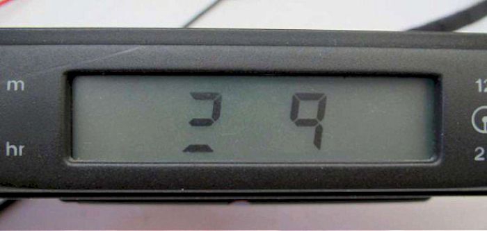
- does your clock look like this? If so then the special glue strip that connects the ribbon cable to the board has deteriorated beyond recall. Some try added pressure but at best this can only be a temporary fix.
so the first thing to do is to find out the connections: On the back of the clock pins are numbered:
Top row right to left: pins 1 to 8 |
Bottom row right to left: pins 9 to 16 |
| pin 1 pin 2 pin 3 pin 4 pin 5 pin 6 pin 7 pin 8 |
black:
levelling switch earth green/slate: dip levelling actuator slate/green: all-close switch orange/purple: driver's seat heater orange/purple: passenger seat heater brown/orange: +12v to clock yellow/purple: hazard repeater yellow/red: hazard lights? |
pin 9 pin 10 pin 11 pin 12 pin 13 pin 14 pin 15 pin 16 |
orange/pink: pass seat heater state orange/purple: driver seat heater state white/red: ign +12v to level switch red/light green: dimmer override slate: security active led red/pink: general illumination black: earth black/pink: logic ground |
Dismantling the unit is fairly straightforward
There are 6 crosshead screws on the back of the clock unit. Remove them and prise open the back panel clips.
If some of the segments on the LCD don't work this is probably due to oxidation between the ribbon contacts and the clock PC board. The ribbon cable is glued to the PC board by a special 3M electrically conductive tape that has low resistance on the Z-axis. This deteriorates with age which is the reason so many clocks fail sooner or later.
There is a white plastic cage that pushes the ribbon against the board connections. The general consensus says that you need to increase the force with which to push the ribbon against the clock connections, so try a thin strip of yellow 'post-its' cut to fit between the white plastic cage and the ribbon in order to ensure the ribbon is forced against the clock connections.
Others have used a piece of pizza box or credit card. Dimensions of whatever you use will probably only be about 50mm X 5mm X 2mm. It's a wee bit fiddly. The 'post its' helped a bit because they stuck onto the white cage.
Apparently the "glue" used to connect the ribbon to the board deteriorates with age; pressure only overcomes this temporarily. Better is to remove the ribbon cable from the board and gently clean up the contact surfaces with fine wire wool (or an ink rubber, but I haven't seen one of these for years). Then selotape it back in position and apply the pressure as above.
To test the clock only on the bench, use a spare connector. Connect 12 volts between pin 6 and the earth pins 15 & 16. Hopefully all the segments are now working?
Now tell me why the a/c unit never seems to have the same problem!

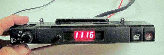
The original clock before modification -
OR - plan B - is to insert a modern LED unit into the old clock - I used eBay item #260824537860
The project needed a bit of care and araldite, some minor rewiring and a smaller pushbutton

- and this is how it looks when fitted into the car - by day (very much clearer than it appears in the picture)
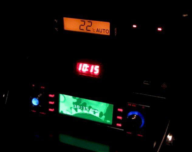
- and by night