The AJ16 Engine
Crankshaft Bolt removal:
The crankshaft bolt requires a substantial 15/16" AF or 33mm socket, a substantial ¾" breaker bar and length of strong pipe to fit over the breaker bar.
Firstly, remove the under tray and radiator fans.
I then removed the crankshaft bolt using a pipe over the breaker bar, placed against the floor. The pipe allows infinite adjustment to ensure all is tight and you have a good angle on the bolt. Remove the fuel pump fuse (trunk fuse box) so the engine won't try to start and then one "bump" of the starter and the bolt came free.
To get the damper off I used two levers against the sump casting - naughty but its held in place by a woodruff key so slides off (fairly) easily. If you must use a puller, locate the legs on the timing wheel, not the pulley, as you could damage the damper.
To re-torque the bolt you must prevent the crank from turning. The Jaguar tool is a bar that bolts to the balancer and braces against the chassis to keep things rigid. However it is unlikely to come undone if you use a heavy hammer and/or impact tool and Loctite.
If you have been working on the timing chains then now might be the time to turn the engine over manually to make sure the valves aren't getting too friendly with the pistons.
Temperature sensor: the one that controls the ECU - NOT the dash gauge
A new temperature sensor: part no: LHE1600AA
Iced water = 5360 ohms
Room temperature = 2800 ohms
Boiling pan of Water = 195 ohms
Mine: engine cold (10°C) - about 3,000 ohms; engine hot - about 500 ohms so about right.
Spark Plugs and Coils: misfires
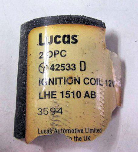
<----- This is the label off a genuine Lucas original coil
I use NGK BCPR6ES gapped at 0.030" (spec is 0.036" but the narrower gap is easier on the elderly coils!).
BCPR6EIX is the Iridium equivalent - see here for explanation of NGK nomenclature.
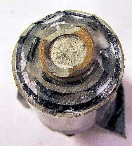
<----- This is a coil being cut open - the whole inside, including the active components and the coils, is rigidly potted so not serviceable.
The FM Radio ticking noise turned out to be a badly corroded coil pack tip. I would recommend pulling the boot off all coil packs to check for corrosion when changing spark plugs. All but one was pristine. The corrosion was so thick on one you could not see the shape of the tip.

<----- Lightweight springs make the connection between the coil pack and plug - stretch them a little so they positively fitted on the end of the plug.
Use electronic cleaner at the coil end and brush them clean with a small brass bristled brush.
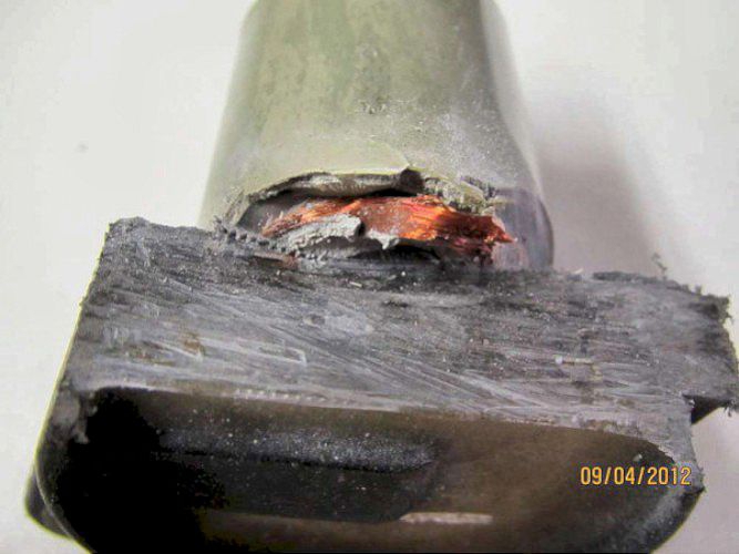
<----- and another view of the sawn-up coil
While you're at it make sure the gaskets that fit between coil and cam cover are secure and that all electrical connections to coils are clean and secure . . . . . they live in a pretty hostile environment heat wise.
Individual coil checking: from Neil Maldon
If you have an oscilloscope with a CURRENT probe, take the plug cover off and check the current pulse on each coil pack.
It should be solid i.e. a sharp rate of rise on the leading edge and exponential decay for a period and a sharp cut off at the end. Any fluttering and/or rise and fall within the pulse indicates a failing one.
or see here if you want to go into real detail!
High Idle: from Mike Jones
Can be caused by a faulty Throttle Position sensor - quite possibly intermittent
OR can be caused by a faulty ISCV (Idle Speed Control Valve) - externally visible on outside of throttle body:
Idle speed OK (around 700 rpm) when running up to normal operating temperature (closed loop) but when taken for a run, idle speed increased to around 1600 rpm.
Checked throttle butterfly returning and not snagging or sticking. Checked inlet pipework post MAF for vacuum leaks but unable to fault.
Plugged in OBD2 via laptop (using Proscan). Noted that as soon as engine running in closed loop control MAF reading gradually increased from 0.05 to 0.07 (sorry can't remember the units). This indicated to me that ISCV not stepping correctly.
Removed throttle body, then remove ISCV and the Throttle pot (very carefully!!). Throttle body surprisingly clean but gave it a good clean with cleaning spray. Sprayed Throttle Body pot with contact cleaner. Cleaned ISCV then checked the two coils. Both checked out OK at around 50 ohms.
Plugged ISCV in and keyed ignition on then off. Noted that ISCV piston motored in then out as it should do. Decided to re-assemble everything and refit.
Fired up the engine but fault still present and same symptoms.
I had a spare ISCV (ebay 99p) that I purchased about 5 years ago. Again removed TB then fitted replacement ISCV.
Re-assemble and fired up. Took car on a good run and all OK. Idle speed steady at 700 rpm (park). Have been using for several days now and no further problems.
Seems that original ISCV was faulty but not sure why.
Crank Sensor:
A new X300 crank sensor has a resistance of around 1,300 ohms and inductance of about 1 Henry. The Jaguar part number is LHE1640AA. If the sensor is working, the tachometer should jump up to about 200rpm or so when cranking but not firing.
On the bench, with the sensor connected to a peak-hold DVM, flicking a steel-bladed screwdriver back-and-forth across the magnetized 'pip' in the centre of the sensor's face yielded peak voltages of around 250mV to 300mV depending on the speed at which the screwdriver moved.
These sensors do fail completely but can also partially fail and give confusing and inconsistent problems from no-start to intermittent firing.
My own feeling (without conclusive proof) is that they deteriorate over time. The Crank Position Sensor is a sensitive electronic device stuck out in front of the engine and subject to all sorts of wind, weather and engine heat cycles. Basically it is a coil and magnet - maybe the magnet gets weaker, maybe the coils start losing insulation - who knows?
I did find, when chasing a fault on my 1995 3.2 Sport, that putting a new CPS reduced the problem I had and in fact I continued to use the car for another two weeks before having to diagnose the real fault.
So my guess is that the waveform off the new CPS was much better than the original such that it was able to partially mask the real fault.
Engine Timing the easy way:
refers to the problems I have had in ascertaining the correct way of setting up the cam position sensor (the unit where you might expect to find a distributor) when it took several churns of the engine before it would fire (though it was fine once running).
- pull the crank around (use a 15/16" or 33mm half inch socket on the crank bolt - it JUST fits without removing the fans) until the missing tooth is exactly under the CRANKSHAFT SENSOR (not the POINTER).
- look at #4 inlet cam lobe through the oil filler cap hole - if it is up then this is the correct TDC. If the cam is down (i.e. pushing the valve open) then rotate the engine 360° and check again.
- remove if necessary and reset the CAM POSITION SENSOR so the dimple shows in the window. It is easier to see where you are if you take the top off (20 torx). You should end up with the dimple alongside the coil thingy on the right hand side. When the top is replaced the dimple should be in the centre of the window.
Now the engine starts IMMEDIATELY on the first compression and without jiggling the accelerator pedal.
I initially set the missing tooth against the pointer - big mistake and it wouldn't fire at all. Which leaves the question - why is the pointer there in the first place as I cannot see anything to line it up to.
Although I used a ¾" socket to get the crank bolt off when I did the timing chain guides, this large spanner won't fit when the fans are in place so I bought a shallow ½" socket (15/16") as I was only pulling the engine over.
In my defence, I put everything back "as it was" - the engine was not good at starting before but as it is my first Jag I didn't know what to expect. It now appears that I bought it with the cam sensor set about 120° wrong! No wonder nothing made sense though it proves how good the electronics are!
Oil Pressure Sender:
The sender (part number LNA 5642) is a switch located on the side of the engine block, underneath the inlet manifold and next to the oil filter, and can be identified by the single wire lucar connector and a large diameter fixing nut. Removal is simple from underneath after pulling the wire and using a large socket.
Early X300's had a true pressure sensor (DBC 5513), which is apparently prone to erratic readings as a result of the carbon track of the potentiometer wearing out. Because of this, and customer concern over reduced oil pressure at idle, which is perfectly normal, later (1995 onwards) X300's and dealer repaired early models had the simple pressure switch fitted instead. This is linked with software reprogramming the instrument pack to cause the needle to sit either at the mid-point, or at zero dependent on the switch.
Today (2010) it is still possible to retrofit a complete late (1990-1994) XJ40 instrument pack. If this has not been reprogrammed then it fits exactly (basically the same unit) and you get proper oil and temperature gauge readings. You will need to fit the earlier pressure sender (DBC 5513). Tighten with a 19mm crowsfoot spanner or an 18mm if a pattern version - you will see why when you try to do the job!
Having proved this works, and the meters worked well, I was eventually forced to give up as it raised a number of issues with some of the warning lamps and the computer switching - See this page
Oil leaks near filter (XJR):
An oil leak which looks to be coming from below the oil filter housing might be from the bypass pipe which is the little half do-nut thingy below the filter housing.
A single, central nut allows the pipe to be removed (kind of a U bend pipe) and you will see clearly an O ring on each end. These degrade over the years probably with heat etc and it's a simple case of replacing them. don't use EPDM rubber rings, only nitrile, preferably viton. I think this is the number KSH119530. You don't need to drain the sump although there will be a little oil spillage.
The other path is to remove the "sandwich" of the adapter. One new gasket and 4 shorter bolts and you can eliminate the o-rings permanently.
Camshaft cover: refitting
You will need the cam cover gasket, two semi-circular seals, the six spark plug well seals and 13 seals for the bolts that hold the cover onto the cylinder head.
Sit the new spark plug seals on the cylinder head instead of trying to fit them into the cam cover.
Insert the gasket at the windscreen end and work your way forward to the radiator.
Both the gasket and the spark plug well seals don't want to stay in position but the above should work. Clean the inside of your cam cover especially the mesh oil breather filter.
No starter motor action:
First - wiggle the gearstick in Park and you should hear the relays click in and out; if not then perhaps the microswitch in the centre console is faulty. This is a fairly common fault.
A new microswitch would certainly be preferable to any of the options below!
There are a couple of relays you need to check to make sure power is getting to the starter solenoid. (from Jeff Watson)
Under the bonnet/hood are two fuse boxes with a relay in each box. Towards the front on each fender. The relay in the LHS box is for the horn, the relay in the RHS box is an IGN relay which should ''click'' when you turn the IGN key to ON.
If it doesn't ''click'' swap it with the horn relay and try again. If it does ''click'' the first time the next relay to look at is in the cluster behind the LHS headlight. There should be one with a large white wire with a red trace coming away from it.
It should ''click'' when you turn the IGN key to START. If it doesn't click you can temporarily insert the horn relay into the socket and try it again. If the relay behind the headlight does ''click'' and you get no cranking then the next culprit is the starter solenoid.
Sometimes they stick and won't pull in and sometimes you can free it up by holding the key to START and firmly tapping the body of the starter motor with a large wrench or piece of pipe. The starter motor is on the RHS of the engine towards the transmission bell housing. There will be a heavy duty cable going to it from a terminal on the firewall.
If it is a relay that is the problem then it is easy to replace it. If it is the starter solenoid then you will have to remove the starter and get it rebuilt. :-(
Starter Motor removal: :-(
from Mechaniac - not too much of a pain, once you figure out that one of the two bolts holding it on is removed from the rear of the bell housing flange (and someone hasn't, in fact, sheared the head off the bolt) - a couple of extensions and a universal joint should reach it.
A small mirror would be helpful to let you see what sort of fasteners are holding the wires in place - quite difficult to see in the relative gloom from underneath the car. It's impossible to see anything from above the engine!
One other thing I would mention is that on mine, there was a thick black lead running from the alternator to the large terminal on the starter motor. In the dark confines of under the engine, it was difficult to see it pop off and away when I undid the nut on the terminal. Not realising this had happened, when I re-started the car, the battery light would not extinguish!! Took me a bit of head scratching to sort it out and figure I had disconnected this lead and not re-attach it!
and from Andrew Bernstein, British Auto Care
Under car, tear off the top left corner of the foam insulation pad.
⅜" drive six point deep well 13mm socket, with:
⅜" drive wobbly tip extension, 6" length, with:
⅜" drive to ⅜" drive universal joint with:
⅜" drive extension, 3 ft. length with:
⅜" drive to ½" drive adapter, with:
½" drive breaker bar or long handled ratchet.
Note - in my opinion, it would be better to use ½" drives (if you can get them in!) not ⅜" - and a 13mm IMPACT socket - and an impact wrench.
You don't have to remove anything but the bolt . . . and the starter. They never damage the ring gear on XJ40/X300, the drive just explodes.
OR - access via the obvious route from the top after removing the wiper motor assembly (but be aware this won't work if the bolt is really tight).
No start or erratic throttle response:
Assuming fuel pressure is OK (around 40psi) and the Crank Position Sensor is OK then the next thing that can be faulty (especially over 120,000 miles) is the throttle position sensor (TPS). This is inaccessible as it is fitted under the throttle body.
You will need to remove the throttle body - not a two-minute job. The numbers on mine (1995 3.2litre Sport) are 4TB 42739A and NBC3061CA and 4896
Once the throttle body is on the bench, remove the stepper motor and the TPS. Be very careful as the securing bolts are quite long and are locktited in - remove a little bit at a time and get some PB Blaster or equivalent onto the threads as they become exposed.
The TPS is Jaguar number JLM12074 - it is marked Ford and 70418A and 6J05A and has three wires coming out of the connector:
Black - blue = 3,390 ohms;
Black - green = 495 - 3,450 ohms (moving smoothly as the throttle is rotated)
Blue - green = 67 - 3,050 ohms (moving smoothly as the throttle is rotated)
Also - a useful diagnosis guide from Mick Gannon in answer to "fast idle":
Have you gone back to basic's and cleaned all of the throttle body parts to ensure that the throttle spindle/butterfly valve assembly in the body rotate and close without sticking and removed all grime and oil gum residue from the throttle bore, cleaned all of the electrical contacts, reassembled correctly and made a gasket or used the Hylomar 102 black auto sealant to seal throttle housing to manifold (not stated in procedure but listed in approved sealants) - all of this must be done first along with checking any air leeks into the manifold system.
The system is mechanically simple: a leak downstream of the Air Flow sensor = high idle
The electronics are also simple: you have a supply signal and a return signal to and from the throttle pot (TPS), temperature sensor, Idle Speed Control Valve (ISCV) and Air Flow sensor
A break in signal to the TPS and the engine will not start
Temperature sensor signal break or wrong resistance will give over fuelling
Air flow sensor fault will give no start or weird running
ISCV valve sticking seized or no signal will give a high idle
Notes on O2 (Lambda) Sensors:
For a 1995 Jaguar X300 3.2 Sport - taken from the In Service Exhaust Emission Standards for Road Vehicles
Tickover (@ 650 - 750 rpm): Max CO limit = 0.5% (mine = 0.00% May 2010)
Fast idle test limits (@ 2,400 - 2,600rpm)
Max CO % vol = 0.3% (mine = 0.02% May 2010)
Max HC ppm vol = 200ppm (mine = 8ppm May 2010)
Lambda = 0.970-1.030 (mine = 1.004 May 2010)
Min oil temperature = 80°C
I believe X300 Jaguars use the more reliable Titania type lambda sensors and not the more usual Zirconia type.
see here for an explanation of how the Titania type of sensor works.
see here or see here for explanations of how the Zircania type of sensor works.
and see here for the listing by one supplier - no connection with any of the firms of course.
Difficult plugging and unplugging the lambda sensors? do this modification.
Eddie Birch did the modification this way: I believe I used a 17mm open ended spanner (please double check just before you start the operation) with an approximately 20 degree bend in the 'bar'. The bend allows easier access to the sensors if you are going at them from the underside of the vehicle.
I found mine very easy to release and copper greased the threads of their replacements. I needed, but didn't have, a 12" bladed flat headed screwdriver or equivalent to reach between the engine and the gearbox to prise out the sensor cables from the two clips. The problem is it is very dark in there, so you can't see very well, and the clips hold both the sensor cables and one additional cable in their jaws and these are really awkward to get out.
You will also need three good sized plastic ties to secure the new cables to the new route you choose for them. To embroider the instructions given on the lpg website, and although I still painted both ends of one sensor connection for safety, I did not disconnect the sensor cables from the loom until I was ready to carry out the actual switch over. This minimises the risk of crossing over the sensor cables and sensors. There is plenty of spare cable to do this after you have freed the old cables from the loom.
There is also a torx secured closed, round clip attached to the lower part of the car. Both sensor cables also pass through this but to remove it from the car to open it to allow the cables to be withdrawn would, I felt, be extremely fiddly.
When everything had been readied for the old sensor removal I therefore cut the cable(s) to enable it to be pulled through this clip. When I routed the new sensor cables I cable tied them to the outside of the clip to keep them away from the exhaust. I found that freeing up the old cables from the loom and from the clips was the only awkward part of the job.
When renewed and re-routed any future sensor changes should be much easier.