Rear Damper replacement
Replacing the rear dampers became a must when I discovered (at 120,000 miles) that one had already been replaced and the other was a very rusty looking original
See how others have replaced the rear dampers:
BEFORE STARTING THE JOB:
Do make absolutely certain the car is securely supported as you will need to exert considerable force to persuade some of the fixings to undo! If you end up in hospital you will be unable to complete the job in good time.
also make sure you have a good set of 6-point impact spanners as some (all) of the bolts are VERY tight! I used a Draper Expert 54651 19piece 1/2'' Impact Socket set which is a set of very substantial sockets and extensions for most bolts BUT even so found that some bolt heads needed thinner wall sockets. Don't forget you will need a strong 7mm allen key to remove the calliper .
Also - be patient. The job took me 4 part-days - 1. to start dismantling; 2. to complete dismantling; 3. to clean things, apply rust preventative, clean up threads etc and 4. to reassemble. The fifth day I cleaned and put the tools away - it was surprising how many I had used during the battle!
Optional - use copper-ease or similar when reassembling so you can do the job easier NEXT time!
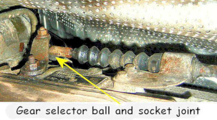
Whilst manoeuvring the car around, the gear selector ball and socket joint popped off at the gearbox end. It was worn out probably due to lack of lubrication in the sheltered area alongside the gearbox. Although not sold separately, it is a separate item and a second-hand one was fitted off an old cable.
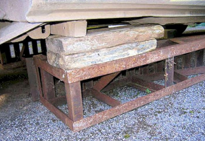
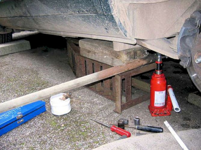
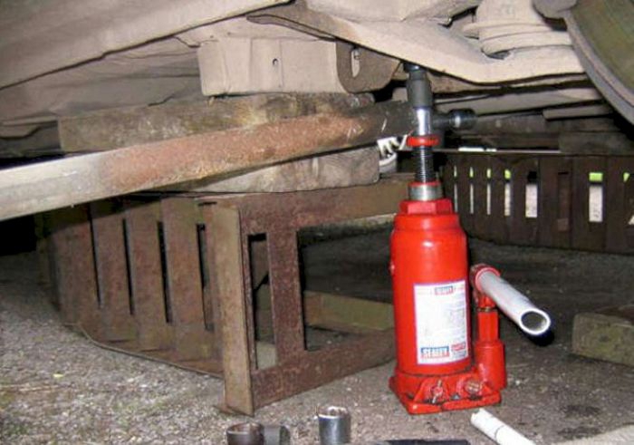
First thing to do is to jack the car up and support the back end securely. If you are on a level floor, axle stands may do - but I was on a sloping drive so was double-careful!
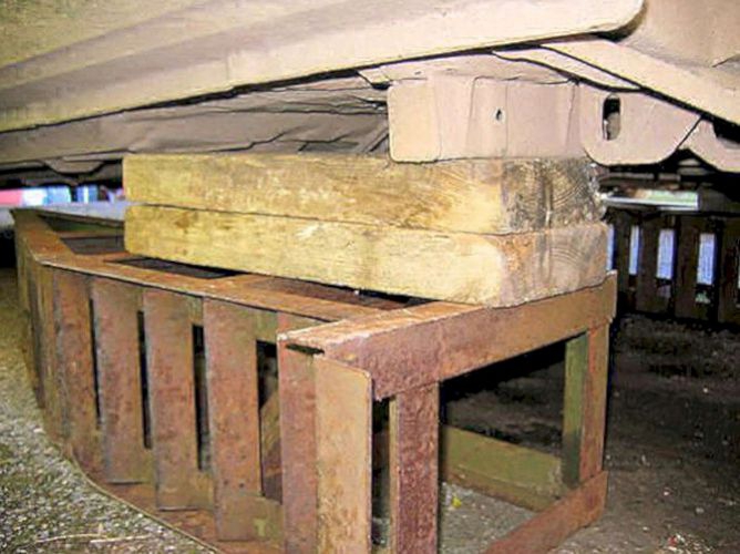
There are only two safe places to jack - under the jacking point itself and under the swinging arm.
First jack under the jacking point and take the wheel off in the normal manner; then use a second jack to support the outer end of the swinging arm. Then replace the first jack by a substantial support.
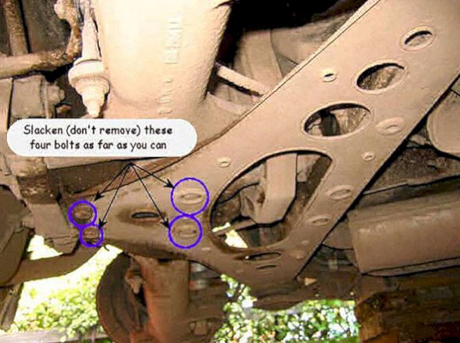
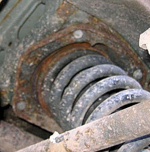
Once the car is securely supported, slacken off only the four bolts ringed in blue as far as they will go without dropping out. Note that the two recessed bolts will require a thin-walled socket - my usual 6 point impact socket wouldn't fit and I had to use one from another set.
Note that slackening the bolts right off meant that the wishbone would drop far enough to allow the spring and damper units to slide out WITHOUT any levering - just.

The nearside and offside anti-roll bar rubbers of the Sport appear to be in good condition so were not disturbed.
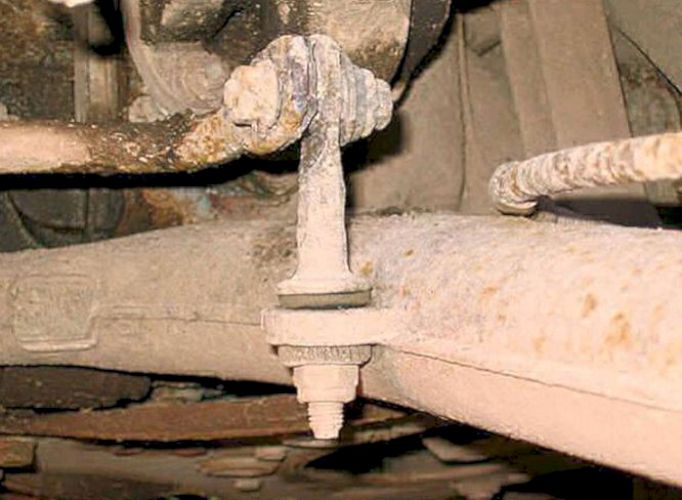
The nearside and offside anti-roll bar links looked rather second-hand so will be replaced.
The nearside and offside mounting brackets under the A-frame mounts have to be removed; they are each held by 4 bolts which can be VERY tight/corroded in place.
At least one of the bolts needs a thin-walled socket to remove as it is so close to the surrounding steelwork.
Considerable force was required to remove the 4 bolts holding the mounting brackets.
One or two needed extreme force which was supplied by a 3 foot tube extension on the normal breaker bar.
To ensure the socket didn't slip off, it was held in place by a jack that actually lifted the car off the support. It is a wonder that none of the bolts sheared and I was able to re-use all of them after cleaning up the threads with taps and dies.
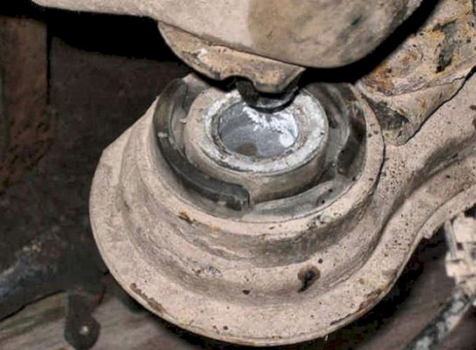
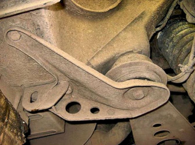
The nearside and offside A-frame mounts can fail, causing metallic noises and a wandering effect on cornering - these seem to be OK. However if you need to change them this technical sheet is essential information - included thanks to Jeff Watson.
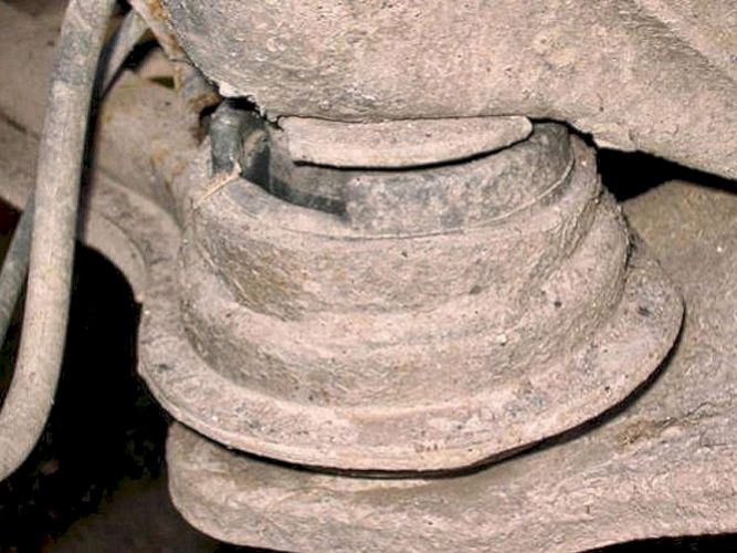
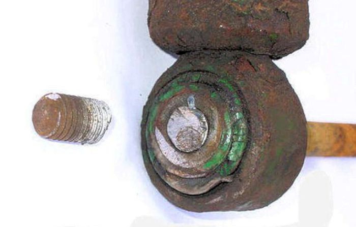
The mounts are rubber bonded onto an aluminium centre and steel outer - not an ideal recipe for longevity and the aluminium can corrode onto the locating cone as one of mine had done.
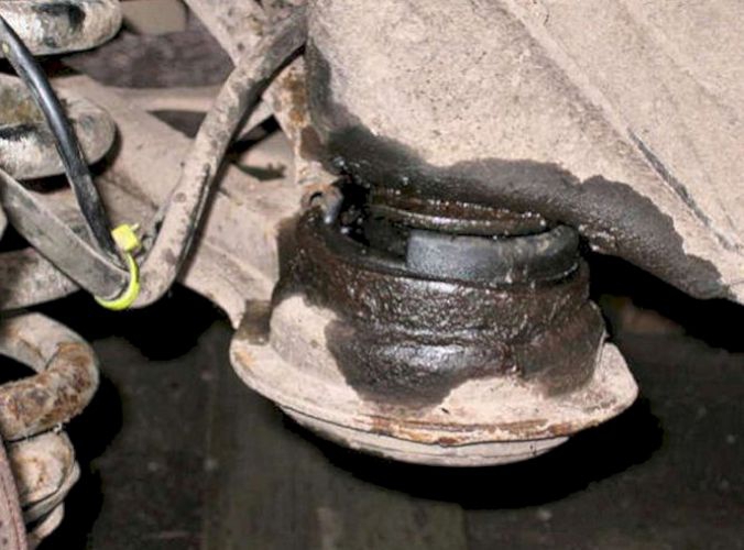
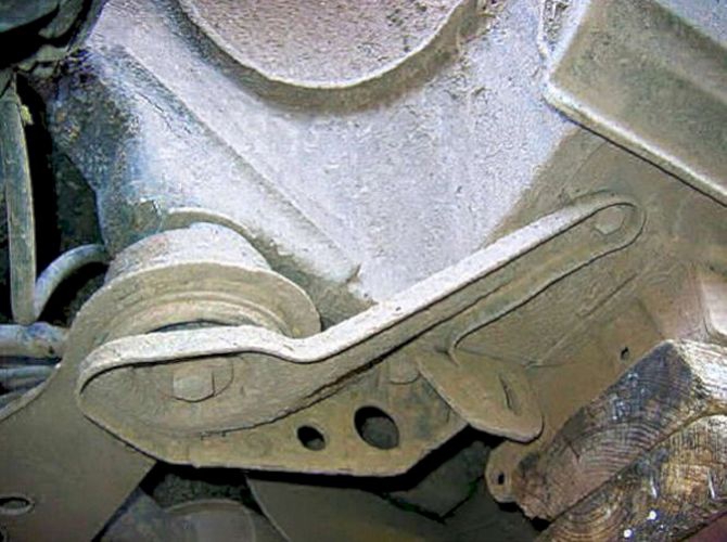
The offside A-frame mount was well and truly stuck and resisted all reasonable attempts to disengage it from the locating cone.

Eventually it released after an overnight soak in PB Blaster and a strong crowbar.
The nearside and offside upper mountings are held in place by 4 bolts. Some need long extensions on the socket spanner with a rocking joint at the bolt end as it isn't always possible to align the socket onto the bolt head.
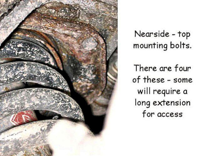
Sorry about the poor focus - access is not the easiest - but gives some idea of the layout.
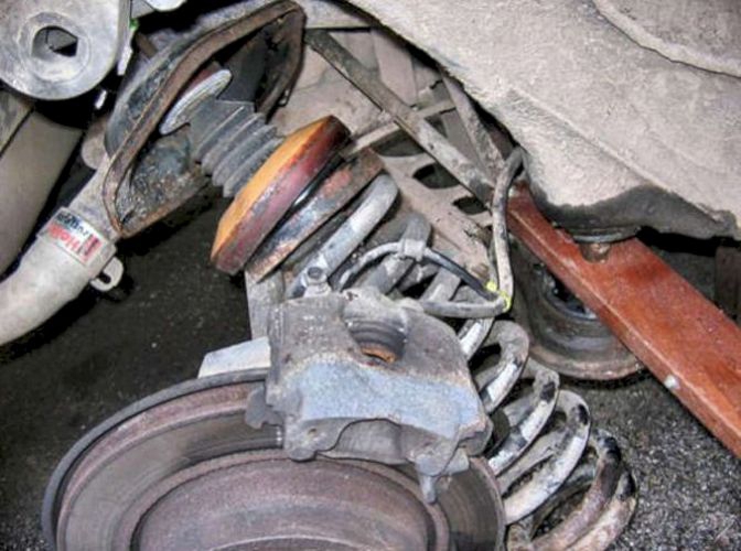
At this stage the calliper mounting (not the calliper , which had already been removed) was still getting in the way so I removed it which gave me more space to manoeuvre. I found the best way was to lower the spring and damper assembly as far as I could, then pull the damper assembly out of the top. It was then relatively easy to "unscrew" and remove the spring.
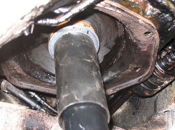
Once the spring had been removed, the top mounting and damper assemblies followed. The KYB has a rigid lower mounting - naughty!
The offside damper was well and truly seized onto the mounting bolt. Because of the rubber mount, hitting the bolt with a hammer was ineffectual so the bolt had to be cut up.
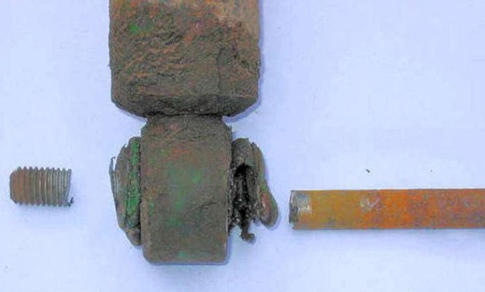
I used an angle grinder though an electric saw would have been better if I had one.
Having - finally - released the mount and the lower damper mounting, the spring and damper assembly started to come out. I lowered the spring as far as it would go and then lifted the damper assembly out of the top. After that it was easy to wind the spring out.
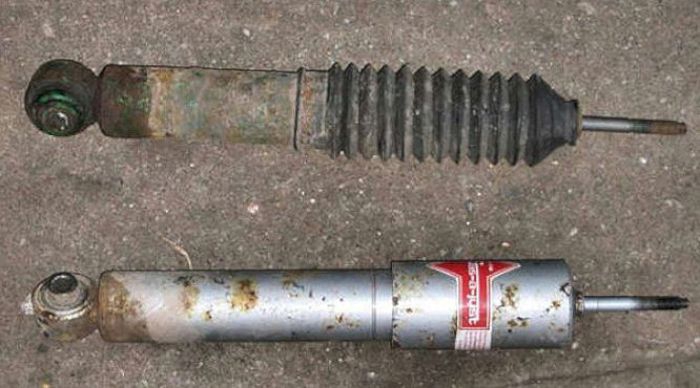
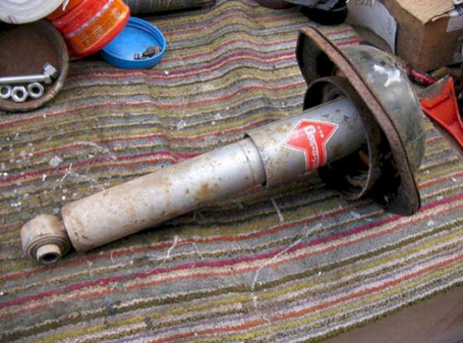
As can be seen, the dampers were mismatched - the original damper was rather weak but the replacement KYB seemed stiff and had the rigid lower mounting bush.
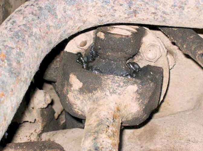
Whilst I could get at them, all four UJ's were greased - for the first time ever, it would appear - one still had a rubber cap on the nipple.
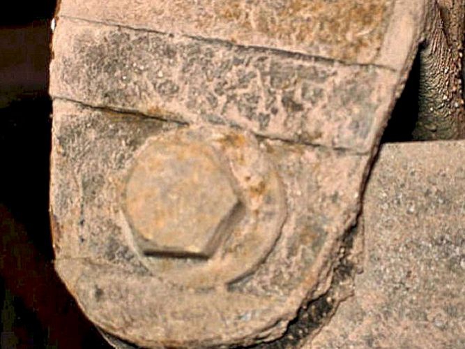
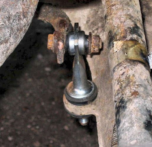
The rear toe-in is adjusted by this bolt which connects the lower wishbone to the axle bearing housing (the fulcrum bearing). Sorry about the poor focus again - no excuse. The integrated eccentric washer on the head of the bolt can be seen. Some remove this bolt, but I didn't touch it as I didn't need to.
I didn't do this but as an aside - these are called the Fulcrum Bearings - Chris Copplestone suggests:
taking the bearings apart is quite straightforward except for getting the bearing races out, if necessary.
Jaguar would have you remove the hub from the car, but I replaced my fulcrum bearings in-situ as have other forum members.
Firstly, you need to mark the position of the eccentric washer in relation to the hub so that on reassembly you can return the toe-in to its original setting. I did this with a centre-pop. Then you undo the large nyloc nut and remove the shaft (you may need a hammer and drift as I did).
Then you can remove the tapered bearings and shims unless they are rusted lumps. Now if the bearings are OK, then simply clean everything up, regrease and reassemble. However, if the bearings are shot, then you have to replace them. You will probably need a new bearing tube as well (as I did), but the shaft can probably be reused with a new nyloc nut.
First you need to drift the old bearing tube out, although if the bearings are rusted lumps you may have to cut it in two to get it out, as I did using a good quality hacksaw blade in a keyhole saw handle - no room for a proper hacksaw.
Then you can remove the bearing races. Removing these races is difficult. I bought a proper inner bearing extractor, but this could not get a good enough grip behind the races to extract them as they are in very tight (the hub casting behind the race gets in the way to effect a good grip) so I used a Dremel and small cylindrical grindstones to cut through the races, which takes time and numerous grindstones. After cutting through each race, I could then use the inner bearing extractor to ease them out.
Usually, you use a slide hammer with these extractors, but with the hub still on the car, there is not enough room, so I simply used the fulcrum shaft to tap the inner bearing extractor through the hub from the opposite side - having cut through the races, they come out quite easily.
Then you need to thoroughly clean up the hub paying particular attention to where the new bearing races will sit. Drift in the new bearing races and reassemble using the original shims (I was already advised on this list that this should be OK as in my case it was) - I used one of the old races ground down to reduce its circumference to a sloppy sliding fit to act as a drift.
Finally tighten up the fulcrum bolt making sure the marks on the eccentric washer and hub are lined up to restore the toe-in.
Another method I was told about to remove the bearing races was to weld a big washer to the inner surface of the race and then drift it out with a hammer from the opposite side - the hole in the washer can be blocked with a suitable nut and bolt

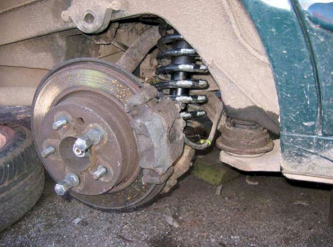
After removing the calliper mount and with the handbrake adjuster backed off through the hole in the drum, the disc/drum slid right off.
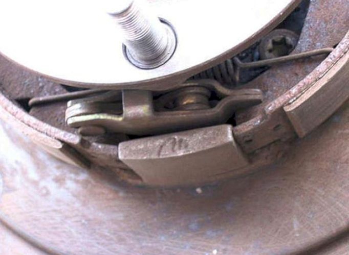
I could see that, apart from a bit of dust, the handbrake was in good condition. Cleaned with brake cleaner and left alone. The handbrake linkages were sprayed with grease and subsequently the handbrake easily passed the MOT test.
With everything removed and cleaned up came the time for reassembly.
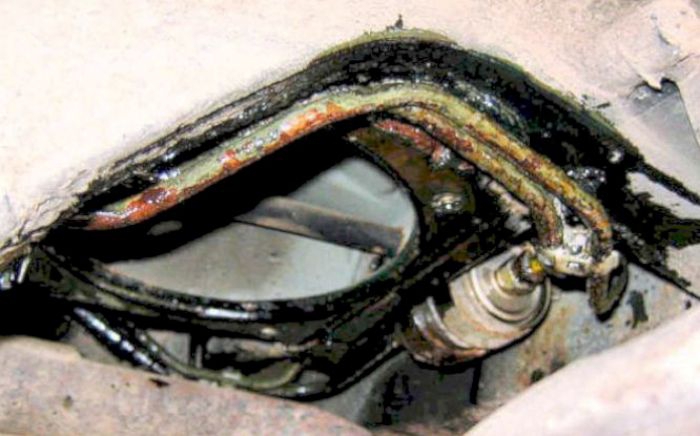
Rusty fuel pipes over the rear axle were treated with POR15 and Waxoyl.
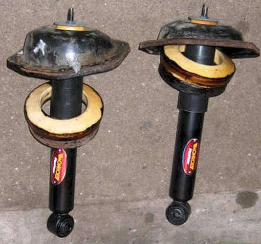
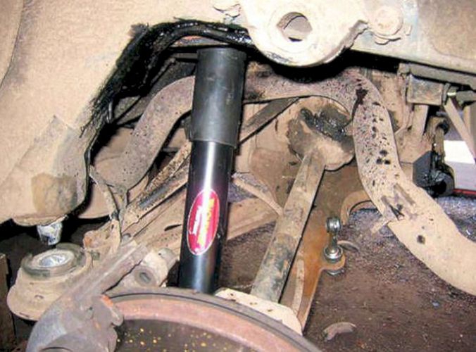
New Monroe Reflex dampers ready to go in - these do have the spherical lower mounting bush which allows movement in all directions.
The nearside damper assembly was replaced and loosely held by one bolt to allow some movement . . . .
. . . . whilst the spring was pushed into position.

With the calliper mount out of the way there is plenty of space to put the spring back in. The spring was lifted into place and the damper and spring lifted onto the swinging arm. Easy!
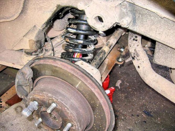
I put the spring in upside down at the first attempt - but with the calliper mount removed and the damper hung from one of its mounting bolts, it proved very easy to correct!
The roll bar links were replaced . . . .
. . . . and the offside is completed after replacing the calliper mount and calliper .