WON'T START - First Steps
The crank position sensor is always one of the first things to suspect should the engine not start - I carry a spare in the boot as they are so often the cause of failure. Several have suggested that they should be a routine replacement at 100,000 miles or ten years whichever comes first.
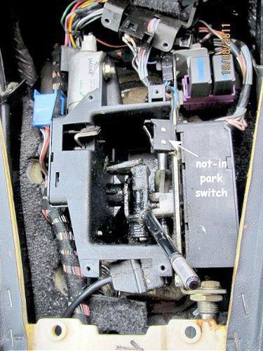
Try waggling the gearstick in Park as the not-in-park microswitch can fail or go out of adjustment
To adjust - remove the ski-slope, the gear knob and the top of gear change unit (4 screws). Gently bend the microswitch operating arm so the gearlever closes the microswitch when in park (see picture).
also check that the Tachometer needle moves when cranking, if not then could be the Crankshaft Sensor. Stuck out on front of the engine, this tends to fail with age but can give a no-spark condition at any time. See this page for further information
Information provided verbatim by Gerald on the Jag-Lovers forum as initial first steps to be taken if it won't start.
Here is a list of relays I think you should check (by substitution with a new one, if possible). Also some other items to check which could posssibly be causing problems.
A critical relay is in the RH under-bonnet fusebox. This one switches the supply to the starter relay and ignition coils (via fuse 12), also the oxygen sensor heaters (via fuse 14).
Whilst you're in that fuse box, check the condition of fuses 6, 11, 12, 14. These carry supply current to various parts of the engine-management system.
Also critical is one of the sealed black relays in the row immediately behind the RH headlamps. It's called the 'ECM controlled relay' and it switches power to the injection system. It SHOULD be the extreme right-hand relay of the group but it has been known for the order of the relays on the bracket to change. To be sure of finding the right one, look for the relay that has 4 wires of colours brown-yellow, brown-orange, black-lightgreen and brown-purple going into its base.
There's the fuel-pump relay which is known to give trouble at times, although I'm not sure that your symptoms point to that. Still worth checking, though. You'll find it in the fusebox in the boot. It's a black relay on a red socket. I think it's the third from the rear in the row of 4.
Also worth a check is the relay in the RH heelboard fusebox which switches the supply to the OBD2 socket and fuel pump relay(via fuse 10).
The fuse boxes (and starter) are supplied by a network of very thick cables from the battery positive terminal. Joints in these cables are bolted using bolts that go through various bulkheads. These points are notorious for corroding (see the archives) and give rise to all sorts of electrical gremlins, one of which is that the starter won't operate when it should. Note also that the thick connection from the battery negative terminal to the bodywork has been reported to suffer the same problems from time to time and will give rise to some equally odd happenings.
Finally, don't forget the white 13-pin connector behind the RH headlamps. Check it for corrosion, particularly the pins connecting to the green-black, brown-yellow, white-pink and brown-orange wires. Problems on these connections will cause engine-running or starting difficulties.
There is a Jaguar Technical Bulletin outlining the actions to take if this connector deteriorates
Connector PI1 (13-way Econoseal III LC white, located behind RH headlamps):

my 1995½ - the white connector is lower of the two

Jaguar recommend moving connector up to here
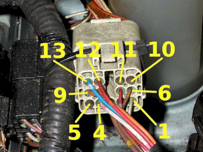
Pin-out of the white connector
Pin 1 - white-yellow, air-con single pressure switch to inertia switch.
Pin 2 - green-black, fuelling inhibit from ECM to SLCM
Pin 3 - brown-yellow, from fuse 11 to ECM relay contacts
Pin 4 - white-pink, from fuse 12 to ignition coils & starter relay
Pin 5 - white-orange, evap valves (only on V12 ?)
Pin 6 - brown-orange, from fuse 6 to ECM relay coil
Pin 7 - red-slate, washer jets temperature sensor
Pin 8 - orange-slate, oil pressure switch
Pin 9 - orange-pink, temperature gauge sensor
Pin 10 - (no connection?)
Pin 11 - pink-black, 2nd fuel pump relay (only on V12)
Pin 12 - red-orange, RH fog lamp
Pin 13 - blue-white, LH main head lamp
The colours listed are as per the circuit diagrams on the CDROM. Of course, it's not unknown for reality to be somewhat different to what the paperwork claims!!
Early cars (like my 1995½) had this connector fixed to a metal bracket quite low down and it was prone to filling with water. Later cars had the connector strapped up to a wiring loom a couple of inches above the original mounting bracket, presumably in the belief that water was less likely to find its way into the connector.
It might just be worth mentioning that the relays in the fuse boxes are themselves powered up via the inertia switch. If that should be intermittent (although I don't recall any reported cases of this), it could cause all sorts of failures . . . .
The immobiliser system - (from Steve, Jags on Gas - several posts August 2011 and December 2011)
The Immobiliser system elements are the key mounted chip, the security module mounted inside the NSR (LHS) wing, the exciter ring around the ignition barrel, the ECU (RHS kick panel) and all the wiring in between.
The chip in the key has no power of its own (batteries are not used in the key) so the chip must be powered up to reveal its code by EMF coming off the exciter ring, just like a chip placed under the skin of a pet Dog. The key chip has a unique and non-erasable code which is registered in the security module during set up.
If the chip is not registered to the security module (or the record has been lost) when an attempt to crank is made, the engine will be immobilised.
The immobiliser system is quite seperate to the key fob operated alarm system. Flat batteries in the key fob cannot result in loss of chip registration over minutes, days or weeks as the memory of the unique key / chip code is held within the security module. This module has a CMOS battery for memory retention although all can be lost if the car's battery is flat or disconected for very long (indeterminate) periods.
To find out if a car is immobilised, perform this check
Turn ignition on but do not crank the engine. Observe the orange 'check engine' light in the bottom left corner of the instrument pod. If that light goes out, the car is immobilsed, at least by the starter not cranking the engine if you try to start it.
The fact that other systems like wipers, lights, windows etc. will still work can confuse the issue. The fact that they are working means nothing at all. The engine alone is immobilised.
*Apparently cars built for the U.S. market do not have this immobiliser system.
The most important thing to understand by far is that the immobiliser operates (or does not operate) a disablement system within the ECU. Imagine it as simply switching a wire. The reason for my separation of the two systems using two different labels is that the car's engine can be disabled even though the immobiliser system is working and the chip-in-key has been accepted.
Immobilisation = Disablement, although Disablement can occur without Immobilisation.
The Ignition switch
We all get used to thinking of the switch only working in a rotary fashion, but it doesn't. The lateral part of its movement (along the barrel axis) has a switching function too, and for sure that function switches power to things like the electric seat entry function, i.e. before the key is rotated to the first position.
Often, one of the relays behind the RH front headlights stays live all the time if this part of the switch is not cutting the power, draining the battery. If this relay remains closed, the ECU thinks the engine is still running so the car won't start.
Sometimes it is only necessary to remove the switch and free up the lateral function with WD 40 or similar, unless the spring is broken, in which case you'll need another switch.
If you want to prove/disprove this theory before committing to any real work, disconnect the ignition switch before leaving the car overnight.
Door locking with the fob
When the engine is disabled in this way (at least by this ignition switch lateral movement fault) the doors and boot cannot be locked with the fob for the same reasons that they cannot be locked if the boot lid or doors are actually left open. The locking procedure only works when the ECU relay is off (not powered) but won't work if the ECU relay is powered when a request to lock the doors is put made by the fob. In this case, you will hear a refusal 'peep' from the security horn. It follows that a similar problem will be encountered if the boot switch or any of the doors switches are broken, not reporting to the system that they are in fact shut.
Removal of the ignition barrel to free up the igntion switch is done by putting the key in and turning it to position 'I', and then pushing in the little detent pin on top of the outer barrel with a bent pointed tool. The lock barrel can then be pulled out, exposing the laterally moving part of the ignition switch. Naturally the column shrouding will have to be removed to do this. An alternative method would be to remove the ignition switch itself and free it up or fit a new one.