Engine Control Unit
The crank position sensor is always one of the first things to suspect should the engine not start - I carry a spare in the boot as they are so often the cause of failure. Several have suggested that they should be a routine replacement at 100,000 miles or ten years whichever comes first. (further information below)
Engine Control Unit problems:
The car had been on the drive, just below freezing for several days, with a light covering of snow. Car had had no problems starting or running prior to this.
Started fine and went to the local shops. On way home the car started normally but started misfiring and wouldn't exceed 2,000rpm and eventually backfired. Got home OK but obviously not right! Tickover was normal.
With inconsistent symptoms it initially felt like a water-in-the-fuel problem; or maybe fuel regulator or maybe fuel pump or filter or pipework.
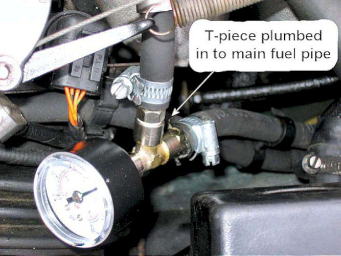
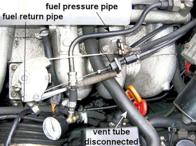
To eliminate these I bought and fitted a Fuel Pressure Test Kit - currently eBay item 250771928164 Simple and effective; I bought the back entry 60psi gauge and have left it in place permanently.

If the engine won't run then by bridging across the pump relay contacts (blue relay in the boot fusebox) showed a steady fuel pump current of 5.4amps and fuel pressure at the injector rail of 44psi with engine off.
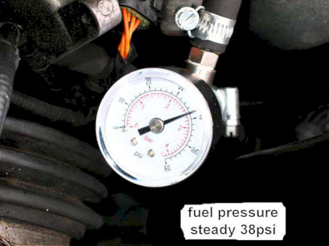
The fuel pressure gauge in the flexible pipe should show a steady 38psi with the engine running, this varies a little with inlet vacuum as the engine is revved up.
Just for completeness - a rogue MAF (Mass Air Flow meter) can give idle dip and lumpiness and/or a hot restart issue. Also check for air leaks in the inlet bellows and be aware that a faulty throttle assembly (throttle not closing fully due to gumming up and/or faulty ISCV (Idle Speed Control Valve) can cause a high idle speed.
To reset the ISCV (Idle Speed Control Valve):
- with the valve off the throttle body and the ignition on you will eject the whole spindle out of the body. The sequence is get someone to switch on the ignition to position 1 then tell them to switch off once the valve has retracted, failure to do this and the valve will then wind forward looking for the valve face, as it is not there it keeps on winding out.
- do not just wind in the spindle into the body you will damage the location of the spindle in the body. With spindle/plunger, sleeve and spring assembled wind into the body slowly when the location just starts to enter the body get a eye glass and align the flat/groove on the spindle with the matching section in the body, then get said person to switch on the ignition, then switch off when the spindle has fully retracted.
High idle has been mentioned several times but a forum search will tell you that you DO NOT need the system reset at a dealer, that is only needed when a NEW TPS is fitted. The system is a closed loop system and gets it's information from the ecu and crankshaft position sensor to maintain idle speed.
First try a replacement valve to correct the idle fault, if that cures it - job done.
If not do the basics: first strip and clean throttle body, clean manifold face and throttle body face's to ensure flat and clean, BIG point - there is no gasket and it is NOT a metal to metal seal, apply .5-1mm diameter bead of black Hylomar automotive sealant to throttle body face around ISCV channel and throttle bore insert 2 top bolts, align onto manifold then push body onto manifold hand tighten bolts insert 2 bottom bolts tighten all bolts assemble all parts, then retest, now although the Jaguar CD does not mention the above use of sealant for the assembly it is an approved sealant by Jaguar.
Also suspected a dying Crankshaft Position Sensor - a fairly common fault.
check that the Tachometer needle moves when cranking, if it does then move on, if not then could be the Crankshaft sensor. Stuck out on front of the engine, this tends to fail with age but can give a no-spark condition at any time. These sensors do fail completely but can also partially fail and give confusing and inconsistent problems from no-start to intermittent firing and restricted rev range. In my case the engine started and ticked over no problem most times but would not rev beyond 2,000 rpm.
The original sensor tested OK - with resistance of 1,250 ohms and inductance of 1 henry. However the replacement sensor seemed to cure the problem - almost! The engine would now rev to 3,000rpm - more than enough power to drive around.
But it wasn't right and still misfired. Things slowly got worse - to undriveable - and eventually unstartable.
Having read on the Jag Lovers Forum that the wiring to the sensors could occasionally go faulty, I decided to remove
the ECU which is behind the drivers side footwell side cover. It is necessary to pull a little of the door seal away, starting at the
tread plate, and prise out the fir tree fixing in the centre of the panel. Then slide the cover towards the back of the car to disengage the two clips which may fall off.
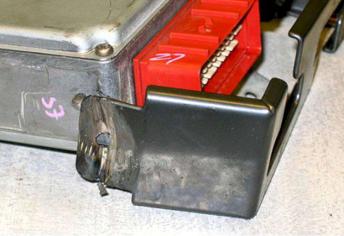
Two bolts hold the ECU in place but then (for me) things got difficult as the two 36-way ECU plugs were covered by a security strap help on by clutch head anti-tamper screws. The head of this type of screw has a normal drive face and a chamfered rear face which prevents the screwdriver gaining any purchase when trying to undo the screws.
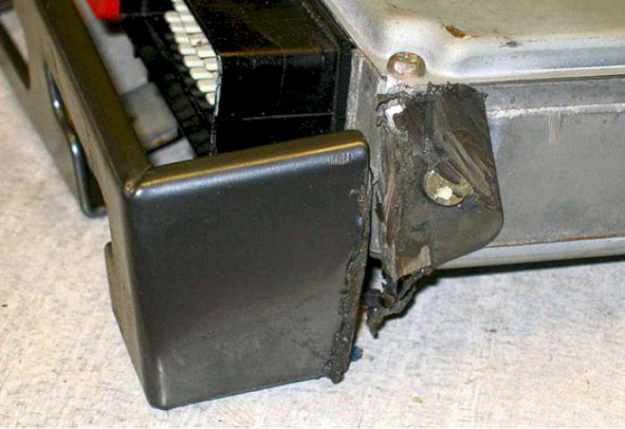
With limited space to manoeuvre, a few minutes work with my trusty angle grinder and the stupid strap was now off and I could get down to fault tracing.
I really wonder how Jaguar did their fault tracing if they couldn't take the plugs & sockets apart? Presumably they gave the customer a new car if the ECU went faulty ?
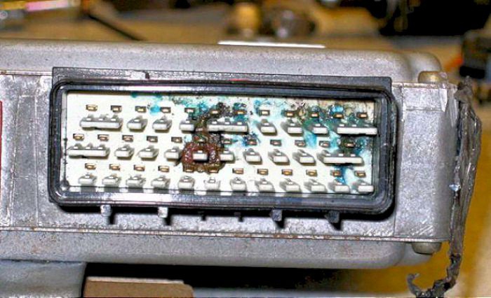
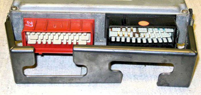
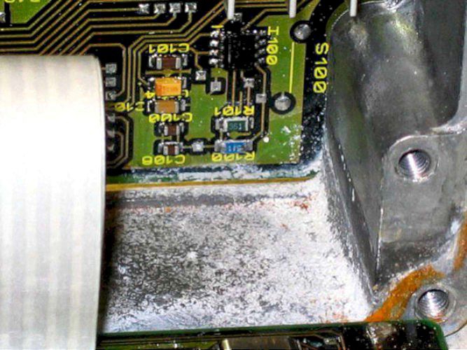
Just as well I persisted - looking at the ECU on the bench I discovered that the black connector has attracted a small amount of water (melted snow ?) and caused serious corrosion.

Over a week or so this drop of water had formed conductive copper sulphate (I think, it was blue anyway) which had partially shorted some of the ECU pins together.
The connector insert was then removed and showed the conductive mess on both sides.
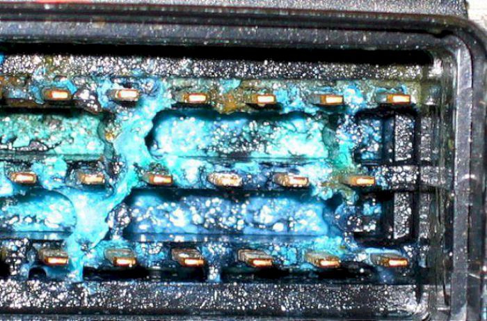
With the insert removed, the true damage could be seen. What a mess; no wonder the car eventually wouldn't go at all!
When cleaning, corroded pin 18 fell off so something had to be done
It is worrying to discover that Jaguar thoughtfully placed both ECU connectors on top of the ECU to ensure that any water would run down into the connector.
Eventually this is almost certain to happen, especially if you have a sunroof and the drains get blocked the overflow runs down the OUTSIDE of the pipes conveniently onto the wiring above the ECU.
NOW we know the reason for the strap - it is to prevent anyone taking the plugs out and discovering this design fault.

the red connector was fine - having no sign of water ingress :-)
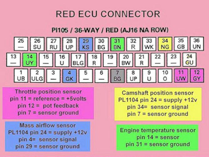
These are the pin-out connections for the two ECU connectors. I bought two 36 way Econoseal ECU PCB connectors

I checked the Throttle Position Sensor and Crankshaft Position Sensor wiring for correct resistances looking back into the wiring from the ECU connectors - both were OK :-)
Crank Position Sensor resistance = 1.282K (note: this is not conclusive as the CPS output DOES deteriorate with time)
Throttle Position Sensor: pin 7-11 = 3.98K fixed; pin 7-12 = 528R-3.27K smooth; pin 11-12 = 3.60K-600R smooth (further comment about the TPS at the bottom of this page)
Temperature sensor: part no: LHE1600AA
Iced water = 5,360 ohms Room temperature = 2,800 ohms Boiling pan of Water = 195 ohms

So - replaced the 36-way black socket on the ECU (don't try this unless you know what you are doing inside electronic modules).
All this complexity just to replace the carburettor and distributor . . . . . . ? and the butterfly and cam position sensor are still there! Is this really progress ?
the ECU was not too bad inside - some dry powder from somewhere (aluminium oxide maybe) but after cleaning should be OK
Refitted the ECU and it worked :-) Thought all problems were solved; replaced the footwell cover and - no start; completely dead. Probably a dry joint (36 connections both sides of the PC board; maybe one didn't take). :-(

The ECU's are SAGEM-LUCAS GEMS6 for a 3.2L N/A auto
The original failed ECU was a (1995) LNA1410BF/211 - 2795. I have now fitted a (1996) LNA1410YD/211 - 2896 which went straight in and worked perfectly :-)
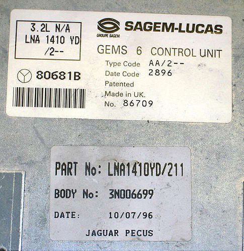
The BF version is shown as superseded and the next one along is the YD, so should be OK. The 211 stands for the automatic version (212 = manual). I've had no problems since and I didn't recalibrate anything.
The 1935 Austin Ten hadn't been started for several months and had been covered in snow and ice, the same as the Jaguar. Fired up right away of course. Well you can't beat progress . . . .
There is some uncertainty whether the ECU needs to be reset by the Jaguar software when you change the TPS
I did it the other way around - fitted a 1996 ECU into my 1995 car when the original got wet. Didn't alter anything and it seems to work perfectly and no measurable change in fuel consumption. Later - consumption seems to have improved from 18mpg overall to 20mpg overall - short journeys on narrow roads in hilly rural area :-)
An ECU costing £1,600 should surely be able to sort out something simple like a change in the TPS surely ? After all, if it can recognise and adjust the timing when the camshaft sensor is set way out it should be able to recognise max and min TPS values? And surely the TPS itself will be subject to some form of quality control ?
I stand to be corrected by an expert - maybe it is understandable that Jaguar would play safe by recommending paying the dealer just to check that everything was within tolerance - but is it essential ? Anyone know for certain?
Have just come across the following from Speedypal:
The EMS (Engine Management System) includes software that is what they refer to as adaptive. We are interested in the TPS adaptive idle voltage.
This adaptive software learns the value of the voltage coming from the TPS when the idle speed is correct. Depending on where the TPS was installed, the voltage will be a little different from where it was with the old TPS. And that's OK!! The adaptive software is designed to compensate for that and other changing conditions as well.
Providing that you got the TPS in approximately the right position the EMS will, within a short period of time (i.e., a few days) learn what the output voltage of the new TPS is when the idle speed is correct. Pretty cool really . But like much of the software in the world, there are situations that are not anticipated (imagine that) and in very rare instances it screws up.
The voltage supplied to the TPS potentiometer is 0 volts and +5 volts The wiper arm of the pot never reaches either of those rails and ends up some place around 5% to 10 % from the mechanical extremes.
That's assuming the TPS was installed in close to the correct position, If it is close enough, the adaptive software will learn the new positions and all will be well again.
and from Steve (Jags-on-Gas)
The TPS is driven (rotated) by a tang much like the end of a standard screwdriver. Because of that it can be wrongly installed, 180 degrees out. I have seen one that read over 4.5V at idle, the result of the fitter rotating it before putting the bolts in.
To ensure correct installation you should see around 0.5V or around 10% on the scanner at idle. You can check the voltage on the green wire with yellow bands using a multimeter. The engine does not have to be running to do this check (better that it isn't). Just have the ignition on, look for 0.5V at idle position and around 4.5V full throttle.