Front Seat Swap
Seats wear out, especially the drivers seat which can, in addition to wearing the side bolster also break the mounting for the switch assembly. For whatever reason, it may be desirable to fit a better condition set from another car.
This was the scenario when (for reasons I won't go into) the immaculate drivers seat on eBay morphed into a pair of good Sovereign ten-way adjustable non-memory seats. One of the problems here is that the original up and down electrics of the Sport seat are not directly compatible with the seat control module on the ten-way adjustable seats.
Assuming the seats come complete, then you will also need the two blue connectors complete with a length of wire from the scrap car - in theory easy to get hold of, but most scrappers take the saleable bits off the cars when they come in and then scrap what remains. So I put in a request for the scrapper to take the connectors off the next ten-way adjustable X300 seats that came in - which he did.
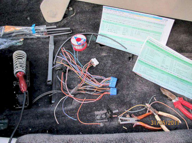
First check that all functions on the replacement seat work - I did this on the bench using a heavy duty power supplier (a car battery would do) after checking the wiring diagrams. In theory all you need is the power and earth leads from the original wiring loom, however being Jaguar it is not as easy as this!
16 years of grime and oily marks from the scrapyard meant the seats badly needed cleaning.
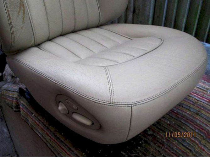
They were cleaned up using Mr Clean Magic Eraser which appeared to be 4 uninspiring blocks of soft foam. In practice they were easy to use and the grime just fell off. I used one block per seat and the blocks were still working well when I finished. I then gave the cleaned seat two applications of Gliptone Liquid Leather Conditioner.
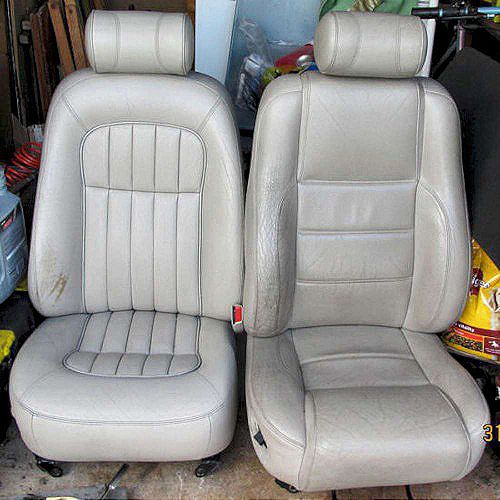
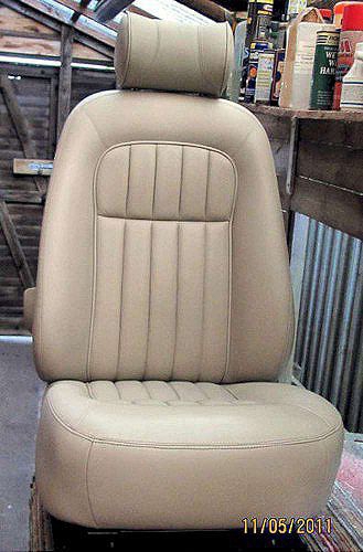
Here is the final result - original Sport seat on the right; cleaned Sovereign seat on the left
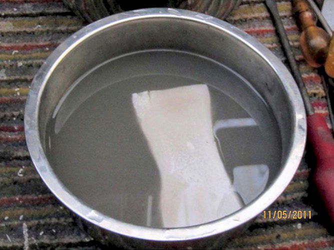
- and the dirty water after cleaning just one seat with the Magic Eraser
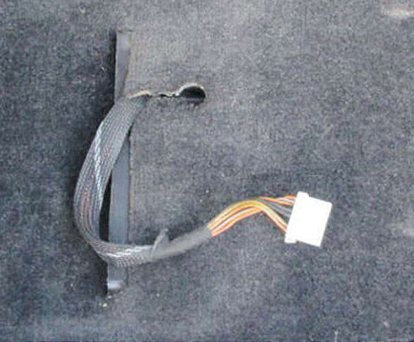
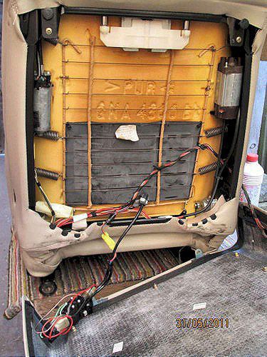
after removing the seats and cleaning the carpet, this is the plug on the end of the flexible cable.
The original Sport loom has a single plug: ML1-D 10-way multilock 070/white
Top row right to left: pins 1 to 5 | Bottom row right to left: pins 6 to 10 |
|
pin 1 pin 2 pin 3 pin 4 pin 5 |
NS NO NG OW OK |
+12v F9 25A RH heelbd +12v F5 5A LH heelbd +12v F4 20A LH heelbrd seat heater relay coil seat heater indicator |
seat heater relay supply motor supply ignore ignore |
pin 6 pin 7 pin 8 pin 9 pin 10 |
SG B B . . |
earth to BPM warning earth earth . . |
seat belt sw . . . . |
Wire colours |
| N - brown | W - white | G - green | Y - yellow | S - slate | U - blue |
| B - black | K - pink | R - red | O - orange | L - light | P - purple |
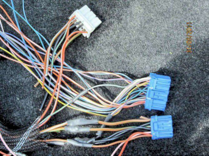
the Sovereign seats have a seat control module
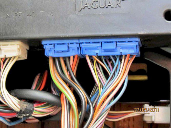
this connects to two blue multilock connectors PL1 and PL2 from the car wiring loom
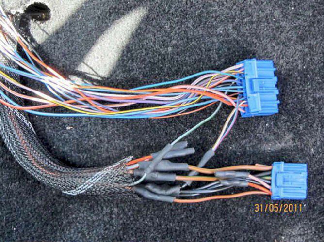
this shows the final arrangement of wires spliced together by soldering and heatshrink tubing.
the connections on the blue 22-way socket PL1 on the seat control module are: (just three wires have to connect to the Sport loom; cut and/or bend the others out of the way)
PL1 top row right to left: pins 1 to 11 | PL1 bottom row right to left: pins 12 to 22 |
| circuit | action | circuit | action | ||||
|
pin 1 pin 2 pin 3 pin 4 pin 5 pin 6 pin 7 pin 8 pin 9 pin 10 pin 11 |
. OK WN UN UP US . UG YB OW WP |
not used seat heater indication earthed by ignition switch no connection no connection no connection . no connection . seat timer control +12v F12 10A RH h/board |
ignore ignore connect ignore ignore ignore ignore ignore . ignore ignore |
pin 12 pin 13 pin 14 pin 15 pin 16 pin 17 pin 18 pin 19 pin 20 pin 21 pin 22 |
KN US OY UR BO . PU . SG KS PG |
. earthed by not-in-park sw logic earth via h/brake sw. earthed by ignition switch . . earthed by brake switch not used seat belt switch earth - drivers door open |
. ignore ignore connect . ignore ignore ignore connect . ignore |
and the connections on the blue 12-way socket PL2 on the seat control module are:
PL2 top row right to left: pins 1 to 6 | PL2 bottom row right to left: pins 7 to 12 |
| circuit | action | circuit | action | ||||
|
pin 1 pin 2 pin 3 pin 4 pin 5 pin 6 |
O K B NG B NLG |
serial communication serial communication earthed +12v F3 20A LH heelbd earthed +12v F4 20A LH heelbd |
ignore ignore conn to earth motor power conn to earth motor power |
pin 7 pin 8 pin 9 pin 10 pin 11 pin 12 |
NO . B . . NS |
+12v F6 5A LH heelbd . earthed . . +12v F9 25A RH heelbd |
module power . conn to earth . . seat heater |
Wire colours |
| N - brown | W - white | G - green | Y - yellow | S - slate | U - blue |
| B - black | K - pink | R - red | O - orange | L - light | P - purple |
To get the seat out - they are heavy and awkward - advice courtesy Lawrence Wedlock
Undo the four mounting bolts (Torx T50 - very tight, can corrode from below. Make sure you have a good bit and plenty of leverage before starting or you will round the splines off).
Now - make sure the rails are as far into each other as possible, ie minimum protrusion.
Lift outside edge to remove the bolt holding the safety belt (17mm socket)
Tip the seat backwards and undo the wiring connectors.
Steering wheel in; headrest down. Seat back at 90 degrees to seat base.
Flip onto outer edge then lead with front of seat so it comes out of the front door on it's side.
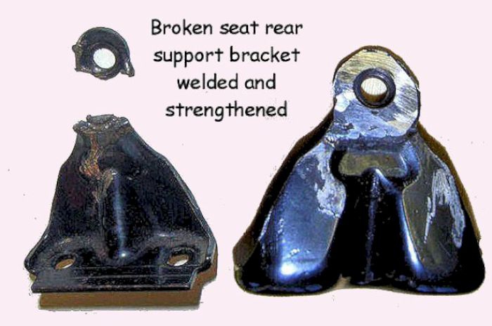
Whilst the seat is out of the car, check the seat bracket at the rear which takes much of the load of the seats. Several instances of fatigue/breakages have been reported. This bracket has been welded up with an additional washer for support. Photo courtesy Lawrence Wedlock
Last job - swap over the connectors. Although I didn't disconnect the battery this might be advisable if you have any concerns about the live +12volt wires.
These two photos show that I did the job one wire at a time to avoid any confusion and also to ensure that the +12volt wires could not touch the earth wires.
SPORT loom (white plug numbers) | SOVEREIGN plugs (blue plugs numbers) |
| ML1 pin 7 ML1 pin 8 |
earth earth |
black black |
PL1 pin 3 PL1 pin 15 PL2 pin 3 PL2 pin 5 PL2 pin 9 |
earth by ign switch earth by ign switch earth earth earth |
white/brown blue/red black black black |
| ML1 pin 1 | +12v 25A F9 RH heelboard | brown/slate | PL2 pin 6 | motor power | brown/lt green |
| ML1 pin 2 | +12v 5A F6 LH heelboard | brown/orange | PL2 pin 7 | module power | brown/orange |
| ML1 pin 3 | +12v 20A F3 LH heelboard | brown/green | PL2 pin 4 | motor power | brown/green |
| ML1 pin 6 | seat-belt switch (driver's seat) | slate/green | PL2 pin 20 | seat belt switch (driver's seat) | slate/green |
Wire colours |
| N - brown | W - white | G - green | Y - yellow | S - slate | U - blue |
| B - black | K - pink | R - red | O - orange | L - light | P - purple |

- and the finished driver's seat loom with blue plugs waiting to be connected to the seat module.
The driver's seat, installed in the car, adds a class touch to the old Sport.
The passenger seat was cleaned with another Magic Eraser and again came up very well. It was also given the Gliptone Liquid Leather Conditioner treatment.

The back of the passenger seat (holding the special order switches to control the front seat from the back) was loose, suggesting someone had been there before.
The reason the back was loose was due to a broken clip which was subsequently resin-glued back on.
Assembly of the back onto the seat is very easy; not so easy to get off. Just two posidrive screws at the bottom; two clever clips to disengage each side near the bottom (press the back in whilst pulling the side of the back outwards) and two fir-tree clips at the very top. The fir-tree clips will disengage by pulling the back downwards, but then you have to remove and reuse or replace the fir-tree clips.
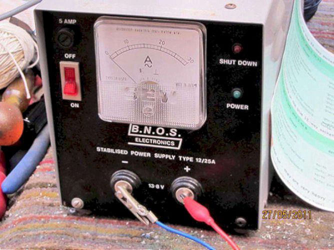
I have a high-power 12volt supply, but a car battery would do to provide the power for testing the seat functions. A meter is helpful to check the current flows to the motors, with a more sensitive meter to check for any leakage current (there should be none as the seats are live all the time to the battery bus).

The complexity of the memory wiring on the two blue plugs is evident, however I did not need the memory function and in fact there were only about 5 wires to attach from the original sport wiring loom.
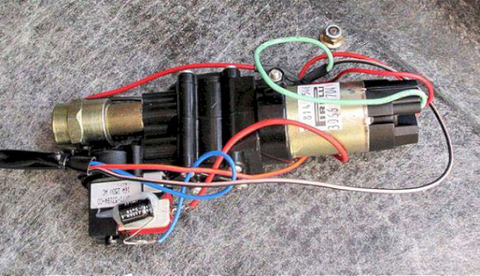
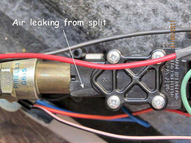
Unfortunately the passenger lumbar pump had failed and was leaking air. Testing on the bench showed that whoever had carried out the tests initially had also managed to blow the driver transistor in the switchpack.
Taking this apart is likely to cause more damage than it is worth so with two faults, the lumbar support was abandoned.