Multifunction Dash Display
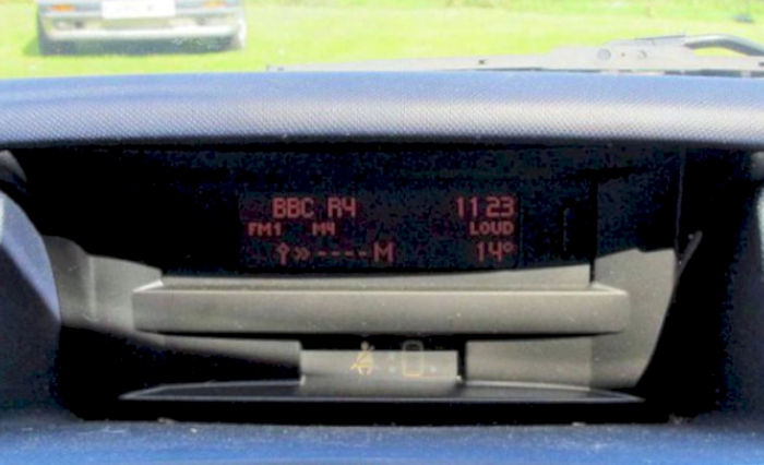
The multifunction display appears rather dim in normal daylight
However it looks much brighter now after finding festoon LED's to fit. I found that 24 small LEDs are much better than three bright LEDs - read on!
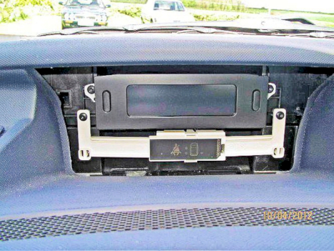
Pull the multi-function display - use a thin flat spatula to prise down the top of the black plastic escutcheon which is just clipped in. Undo the two torx screws and pull the top display forward. Don't drop these two screws or they will disappear for ever! I placed a piece of rag under them as a precaution
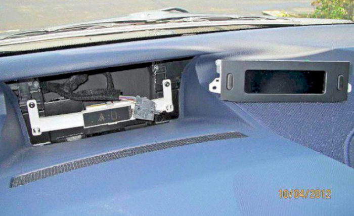
Unclip the cable and release the multi-pin plug - the release is on the cable part of the plug; pull it over the locking lip on the plug and it will lift the connector out of the socket.
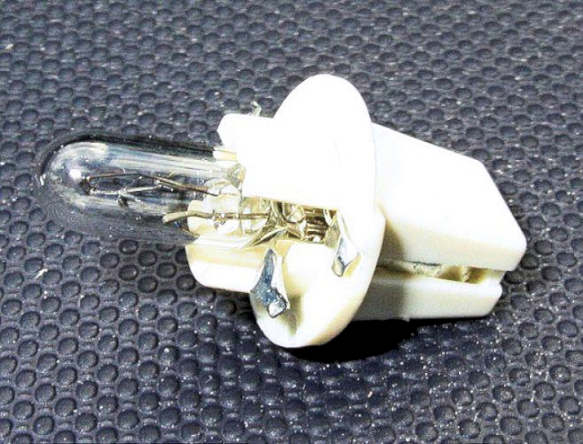
The three bulbs are the miniature variety and look a little different to the conventional 509T fitting. However the common 509T does fit so all three bulbs were initially replaced with high brightness RED 509T LED's. What are the odds against putting ALL THREE in the wrong way around? But I did first time - 8:1 I guess.
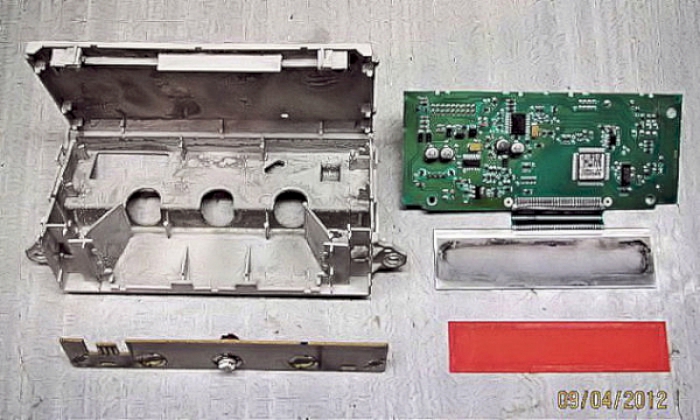
With the display on the bench, remove the front mask and gently open up the unit. Inside will be found a printed circuit board connected to the display by a ribbon cable. The lamp board is plugged in to the printed circuit and gentle prising will release the printed circuit board still connected to the display - lay to one side.

The orange diffuser is glued to the back of the display; it can be prised off gently, but I used it in preference to a white diffuser I had.
Lift out the lamp board (held in position by two plastic clips) - ready for the LED bulbs. Some of the LED's I received were slightly oversize so it may be necessary to open up the hole (I used a reamer but careful filing will do) and adjust the contacts on the LED bulbs if necessary. The advantage of having the lamp board out is that you can see exactly when it fits and the contacts are being made.
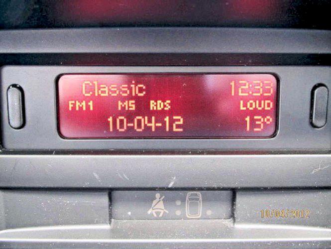
Apart from needing to reset the clock time and date (and losing the trip computer settings) - all is well. The display is certainly much brighter now with the LED's the right way around.

This was good, but I thought I would try one further stage and fit multi-LED festoon bulbs.
I used 2x8 SMD 42mm LED festoon bulbs - but there are many alternatives as here for example
These bulbs arrived with ends that could be unsoldered - so I did . . . .
. . . . this enabled me to solder the boards carrying the 8-leds to the original bulb contacts.
This shows the lamps back into the housing - it was necessary to nip short two of the plastic guides - this has no effect on the security of the board location.
The second picture shows the LED's lit dimly - full brightness upset my eyes and the camera!

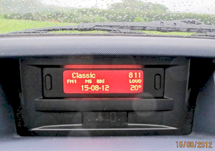
Reassemble and refit the unit in the car. Now we can REALLY see the display!
I could have used a white diffuser but it seemed to allow too much light through so I left the original orange diffuser in place
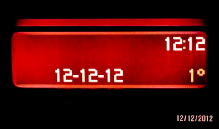
couldn't resist this - taken on 12th December 2012
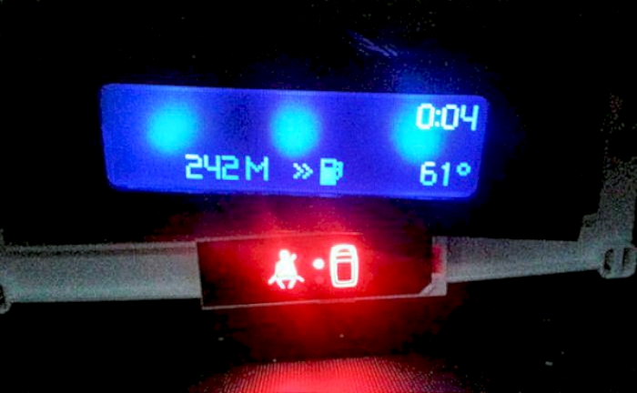
Mike prefers a blue read-out and he did it this way:
After removing the orange filter from the LCD screen, I found the best way to diffuse the light was to lay a sheet of white graphics vinyl in its place. I did try a number of proper diffusing films removed from scrap LCD screens but none of these worked as well.
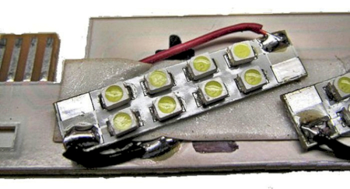
Upon trying a set of LED Replacement bulbs I found they were too focused in one point and created 3 spots of light as you can see from the first photo below.
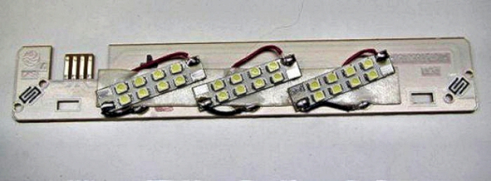
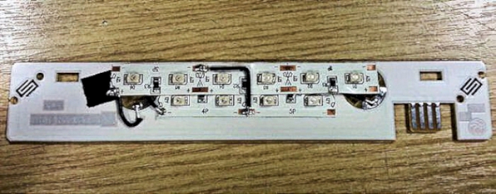
I then opted for a strip of SMD (Surface Mounted Diodes) that were preprepared with resistors from Maplin This is the white version and with the white vinyl any colour led should shine through nicely.
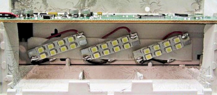
When installing I tested using strips of 6 and 4 LED's in 2 rows (second & third pictures). This arrangement worked well but didn't give sufficient light spread, so the final set-up (not shown) is 3 rows of 6 SMD's and this now gave me the even light spread across the display.
When soldering these strips I picked up the positive from the bottom half of the standard fitting socket (Nearest the connection side) and the earth from the other side. The lighting/button board has a common positive across all the 3 bulb fittings and a common earth across the whole board as you would expect.
The advantage of these SMD strips is that the resistors are already present to drop the volts for the LED's and they spread the light more evenly.
Mike's first test - the three bulbs replaced by wide angle LED's
test two - use multi surface-mount LED's (SMD's)
test three - increase the number of LED's to three rows of 6 SMD's (not shown)
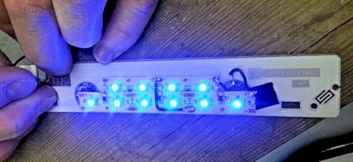
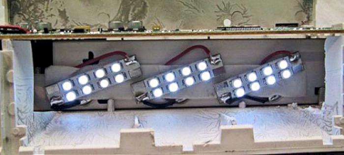
testing the test two SMD array - plenty of well-spread light

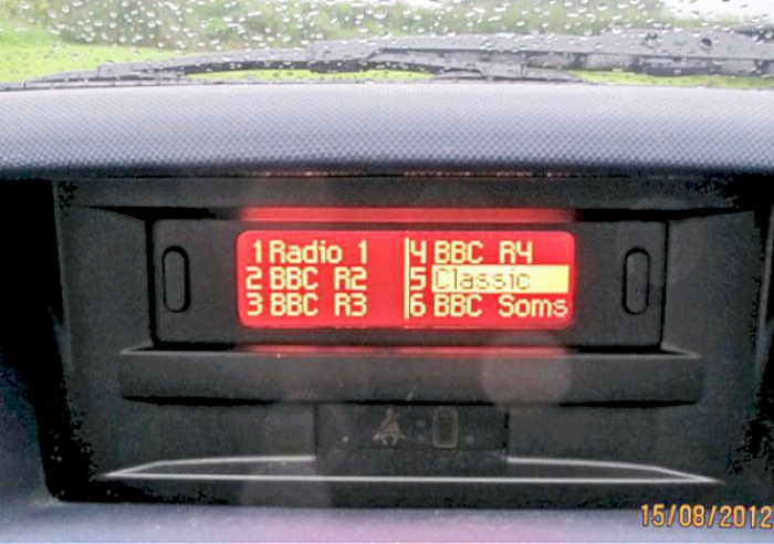
and the finished display - using three rows of 6 SMD's - in blue