
Steering & King Pins
November 2004:
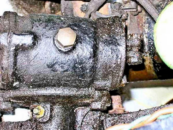
The steering box is one of the last of the full wheel type. There seems to be minimal play so greasing the output shaft (new modern grease nipple) and adding SAE140 oil was all that was needed except . . . .
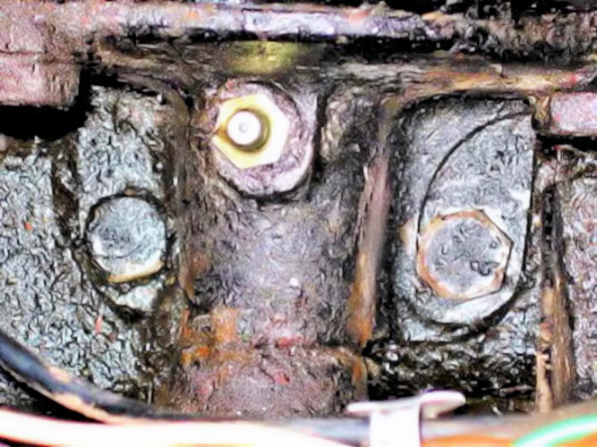
. . . . the box is only held by two bolts into the chassis - it moved about until I tightened the bolts securely - an easy job with an extension on the socket spanner. I hope the holes aren't elongated ..... April 2006 - still tight!

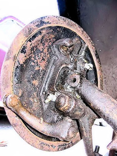
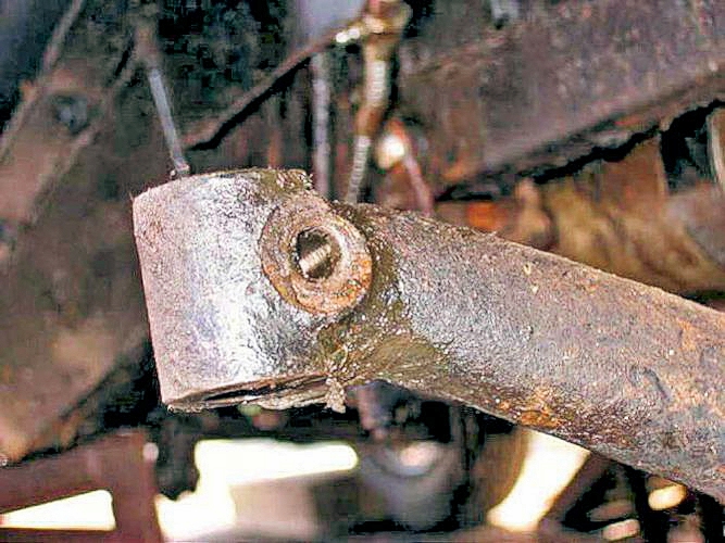
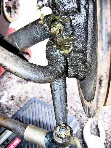
a better picture of the steering box output shaft with the drag link on the end nearest the camera
Although one of the king-pins shows a little wear, the front suspension and track rod ends were only greased.
June 2005:
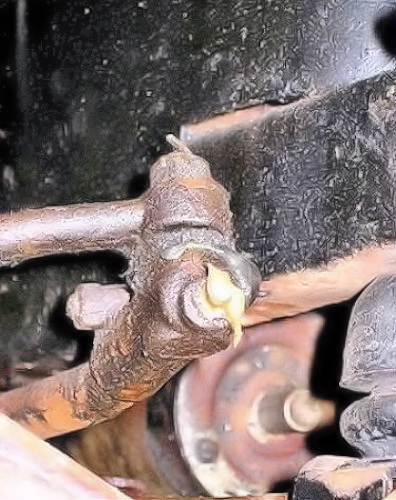
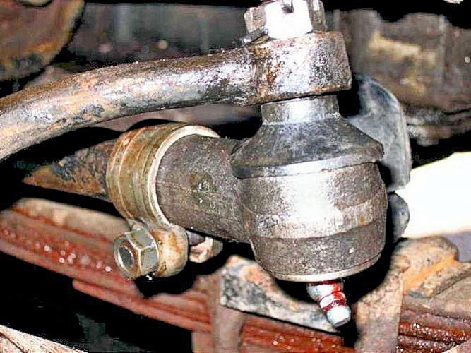
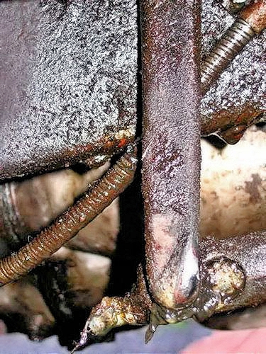
The only MOT failure points were the front drag-link balljoint (which I hadn't spotted) . . . .
. . . . and the offside king-pin (which I had spotted).
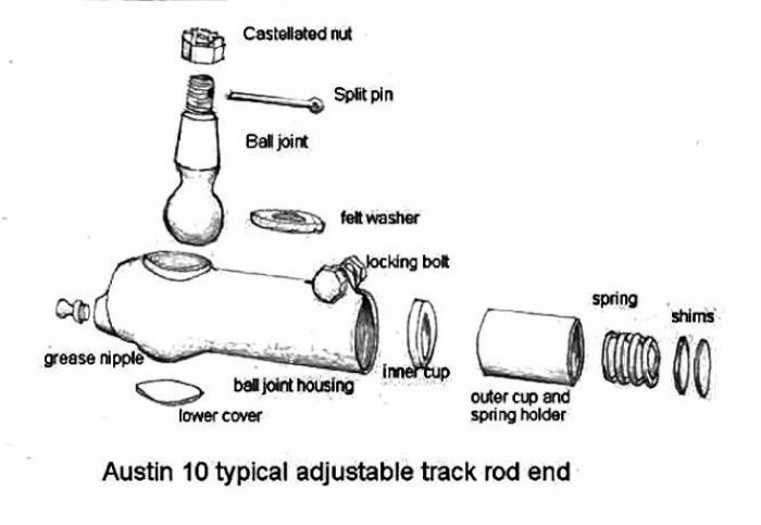
A track-rod end assembly drawing taken from Andrew McMillan's web-site (now taken down). The drag link balljoint seemed OK after I had cleaned it and freed off the spring loaded plunger. I couldn't get the plunger all the way out for some reason (it should come!) to clean it properly but made sure the plunger was free and re-greased it.
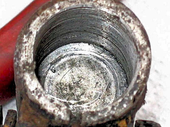
I added a shim (actually a 5/16" washer) between the end of the drag link and the drag link end.

this gave minimal plunger movement when the end was screwed back on.

It would appear that reassembly requires the track rod end to be screwed onto the rod until it tightens solidly against the ball. Then unscrew about one half turn and lock in position with the clamping bolt to give the correct pressure on the ball. The ball should turn smoothly, but with some resistance.
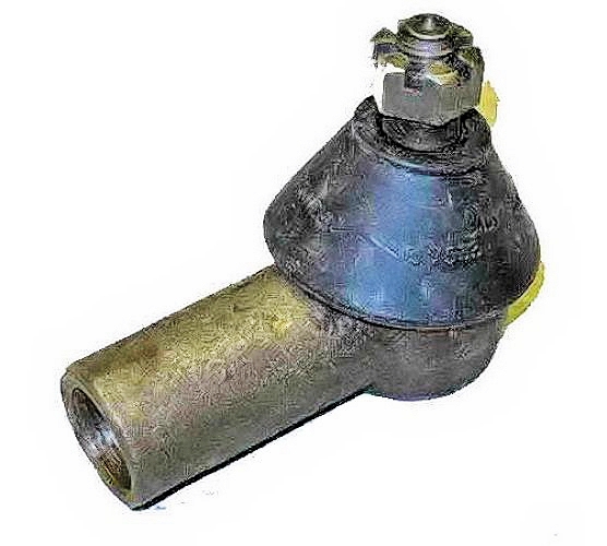
As the track rod ends were of unknown condition and I had problems with the drag link end - I obtained some non-adjustable track-rod ends (these are quite rare due to the obsolete Admiralty 20tpi thread on the track rod and drag links).
I fitted one to replace the drag link one above and both track-rod ends (see below) in April 2006 without difficulty.
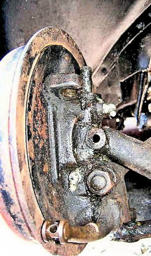
After undoing the dome nut (which is held by a locking tabwasher and takes the whole weight of the car). ---->>
I hadn't looked forward to dismantling the king-pin!--->> but I was lucky - despite having been undisturbed for 70 years, the cotter pin tapped out.
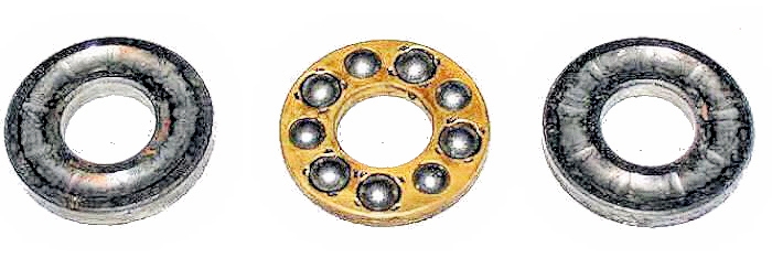
---->> the ball bearing (in three pieces plus the cover) lifted off. The bearing races were slightly indented but on reassembly seemed to run smoothly enough. Surprisingly, they are still available from ATD Club Spares. The alternative would be thick washers; not as good as the original frictionless bearings.
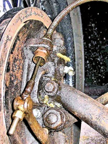
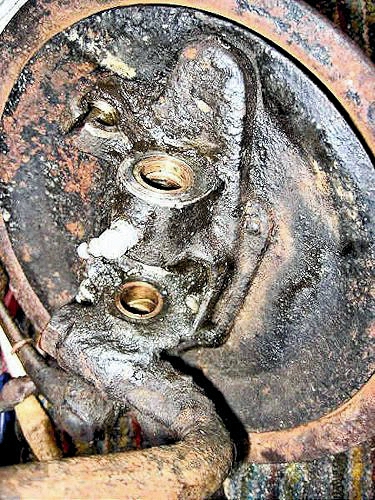
Disconnect the drag link and track rod joints and the brake cable, Picture shows the cotter pin out and everything else clear ready to pull the king-pin out.
Using a spare 9/16" BSF nut (don't use the dome nut as the keyway can cut into the threads) and various spacer washers, the pin was pulled out by tightening the nut. It was moderately stiff but came out easily enough.
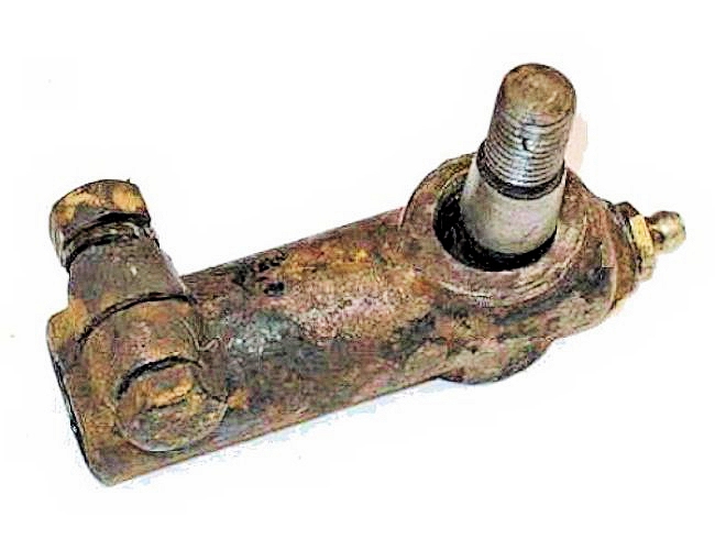
After this the stub axle assembly dropped into my hands leaving the axle eye ready for cleaning up.
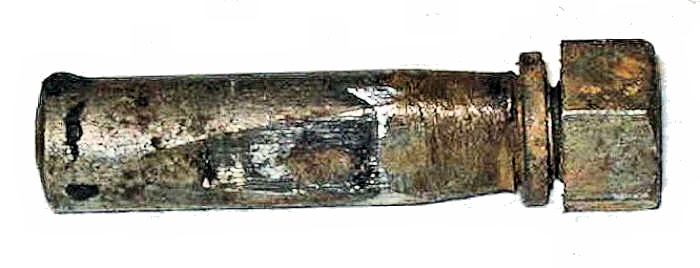
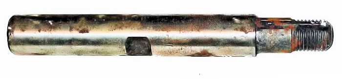
Steel pins usually wear faster than the bushes (they can also corrode in the inhospitable conditions the king-pins have to work in!) - so I replaced just the pin after checking there was minimal play in the bushes.
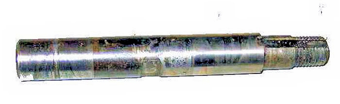
The old pin didn't look that bad, but the small amount of wear at the bottom end is magnified by the time the wheel is rocked top & bottom by the MOT tester.
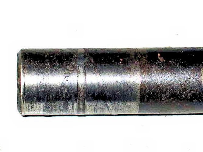
This level of accuracy also means that the pin and bushes must be a very accurate (reamed) fit when replaced
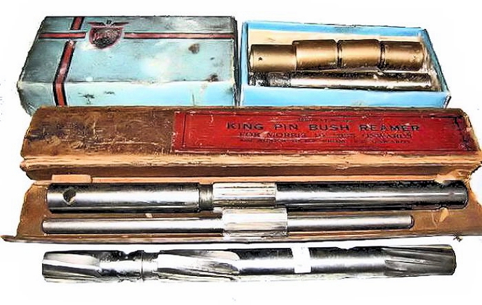
I already had a king-pin kit - one king pin had already been used on the nearside - and I had two sets of reamers ready in case anything need cleaning up.
the new pin needed cleaning up as it had some surface corrosion over the last 27+ years of disuse. Reverse the above to reassemble as they say; it all went back together very quickly
KING-PIN ASSEMBLY DETAILS for the 1935 Ten Lichfield
(note that there were variations over the years)
On the Lichfield, the load of the car is taken entirely on the top bearing; the one immediately underneath the dome nut.
So, from the top of the king-pin downwards:
- Dome nut (with or without grease nipple; doesn't really matter either way)
- Special lock washer.
- Bearing this can be EITHER two thick washers, which obviously will need regular greasing - or the original design of 3-part ball thrust bearing. I believe this bearing is special to the Austin and won't be available elsewhere.
- There should be a felt seal somewhere; I think it fits inside the dust cover to prevent grease getting out and dust getting in
- The front axle eye
- I think there should also be felt seals to fit on the king-pin between the axle eyes, to keep grease in and dust out but not sure of this detail.
- and of course the cotter pin which is the critical bit which takes the whole weight of the front of the car.
The king-pin should be a tight fit in the end of the axle and be locked firmly in place by the cotter pin. Any play here will magnify and lead to eventual failure.
The idea is to set it up so the weight is taken on the top bearing and the dome washer should be adjusted until the axle eye sits centrally in the space between the swivel bushes. Make sure you have a good lock washer and bend it now to lock the dome washer in position. On some lockwashers the tang on the inside that locates into the slot in the king pin can be slightly loose, which allows the dome washer to move slightly - best if it doesn't!
The two critical parts are the lockwasher and the cotter pin.
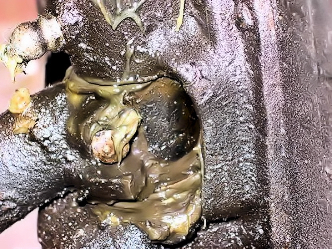
a final point - old hands have recommended that the Bowden brake cables should be oiled rather than greased. So as most of the steering joints and king pins would hold oil as they were "upside-down" - they were oiled. Oiling the king pins of my Rover 90 has worked well - they have never been apart in 216,000 miles from 1955.
Although it is possible to use a grease gun for oil, it can be messy. Proper oil guns are not easy to find and I got an Abnox-Wanner 30960 from a very helpful firm: Stephenslube who unfortunately (Feb 08) seem to have disappeared.
August 2006:
BUT NOTE: - Poor braking led me to take off the front drums: there is a small hole between the lower king-pin bush and the brake cam spindle. So using oil in the king-pins also oils the brake cam spindle AND THE EXCESS RUNS THROUGH ONTO THE BRAKE LININGS! So - use grease as specified!
April 2006:
After working on the front springs there appeared a slight front wheel shimmy at 40mph and above.
The track is given as 3' 9" (45") front and rear, so lining up by eye is possible by looking from front to back - this showed that the wheels were slightly turned-out.
Confirmed by tape measure across the tyres to be ⅛" toed-out. The handbook states it should be 1/16" toed-in at the rims so the track rod needs lengthening.
Original Austin track rod ends are adjusted by dismantling and, after rotating the end to the new position (which must be in line with the other end of course), shims are added or removed to adjust the clearance on the track rod end itself. As both ends are right-hand threads the track rod itself can ONLY be adjusted in complete turns - think about it! The shims adjust the length of the track rod when both ends are in line and the ball clearance (half turn back from tight see above) is correct.
Even so, this is quite a major job compared to the right/left hand thread system on later cars (and indeed 1935 Morris cars!) and requires at least one end of the track rod to be disconnected so that end can be rotated in or out. One turn of the 20tpi thread alters the length of the track rod by 0.05". The steering arm operates at about 4" radius and the outside of the tyre is 14" radius - so one turn moves the outside of the tyre by 0.05 x 14/4 = 0.175" - and so changes the toe-in (or out) by 0.35". So it is quite a coarse adjustment.
What I did was to use two new old stock non-adjustable drop arm ends - so doing away with the need for shimming. These don't have any locking method so after adjusting the rod to the correct length, I drilled through and split-pinned them semi-permanently in place. Checking using the ruler method showed that the toe-in at the tyre is ⅛" - about 1/16" at the rim, which is correct. More importantly - the shimmy has gone!
On right lock, the front wheel just touches the steering drop arm
this could be due to wear on the lock-stop which is a small projection on the axle - OR the drop arm being bent outward.
Cleared by bending the drop arm in a little by heavy crowbar!
Carefully set up, the Austin Ten drives straight, with no bias either way; no shimmy, no wander and good self-centering.
I can see it might be less so if the adjustments have not been carefully and systematically undertaken.